
ESP32 RMT peripheral with 315 MHz or 433 MHz EV1527, HS1572, PT2240 and similar
Control your EV1527 and similar wireless devices with ESP32 and 433 MHz receiver and transmitter, utilizing ESP32 RMT (Remote Control Transceiver)
Today, we will use the ESP32 to capture the signals of our remote control and later send the same signals to the device we want to control. After this tutorial, you will be able to control your wireless device, such as remote garage door, smart plug, etc., using ESP32 with 433MHz transmitter to send EV1527 signals with the help of ESP32 RMT peripheral.
Honestly, the most popular project with ESP32 and 433MHz is the ESP32 Garage Door Opener. So if you came here for this, yes, you are in the right place.
Components #
Before you begin, you will need these components:
| Part | Notes |
|---|---|
 ESP32 microcontroller | Since you are reading a post about ESP32, you will surely need the ESP32 board. Any board should work if you can connect it to your computer with a USB cable to transfer the program. Check here for the comparison of ESP32 chips. |
 433MHz transmitter and receiver modules | There are many 433MHz transmitter modules available on the market and you should use the one that suits your project best, but if you are not sure what to choose, we will take a look at the most popular options. |
 Breadboard and jumper wires | you will need breadboard and jumper wires to easily connect the ESP32 with RF modules. |
 Power source | You will need a sufficient power source for the ESP32, 433MHz transmitter and EV1527 encoder. It can be a battery or a power supply, depending on your project needs. |
 Device using EV1527 or similar protocol | If you want to use this knowledge with the wireless device you already have, for example from your garage door wireless control system, you can later control it with ESP32. |
315 / 433 MHz transmitter and receiver modules #
There are many 433MHz transmitter modules with different specifications available. When choosing a 433MHz transmitter, you will have to consider the following:
- Data rate - it can range from a few hundred bits per second (bps) to several kilobits per second (Kbps), depending on the module.
- Modulation - most commonly used modulation in the 433MHz modules is Amplitude Shift Keying (ASK), but some modules also support Frequency Shift Keying (ASK).
- Output power - different modules provide different output power, which will affect the range of wireless communication.
- Operating voltage - most modules operate on 5V logic. While ESP32 works with 3.3V logic, it is best to look for the 3.3V 433MHz module, but it is possible to make the 5V one work as well.
- Antenna - while normally, the 433MHz modules have integrated antenna, if you need a better range, you should look for a module that can connect an external antenna.
The following two boards are the most widely available and most used modules for DIY projects:
| Part | Notes |
|---|---|
FS1000A / MX-FS-03V | Transmitter has a 10 Kbps data transfer speed and 10mW of transmission power and operates on 3.5V-12V. The receiver operates at 5V DC and provides a receiving sensitivity of -105dBm. |
 SYN115 / SYN480R | Transmitter has a 10 Kbps data transfer speed, 10dBm output power and operates on 1.8-3.6V. The receiver operates at 3.3-5.5V DC and provides a receiving sensitivity of -107dBm. |
Both of these options should be perfect for your DIY project with ESP32, the transmitter can be used with 3.3V, which is perfect for ESP32, while the receiver operates at 5V, you will need to step up the voltage.
Keep in mind, that we are providing only the 433 MHz options, but if your remote control system uses 315 MHz, there is not much of a difference and you can use these instructions as well.
The ESP32 Remote Control Transceiver (RMT) #
If you have never heard of RMT before, you might be wondering what is it... The RMT (Remote Control Transceiver) is a specialized hardware peripheral on the ESP32 chip that was initially designed to provide a simple and efficient way to generate and send IR (InfraRed) signals. However, due to its flexibility in the data format, it is now used for a variety of wireless radio frequency (RF) communication protocols, including PT2262/PT272, HT12/HT12D, EV1527 and more.
It consists of two channels, which can be used to generate and receive signals at the same time. Both channels have a dedicated set of registers, which can be used to control the modulation and timing of the signals.
To put it in use, you will need to have the RMT library installed. It is included in the ESP32-Arduino core, so if you have programmed your ESP32 board with Arduino before, you should already have it. If not, here are the instructions on how to install it with Arduino IDE:
- Open the Arduino IDE and go to the File menu.
- Select Preferences.
- In the Additional Boards Manager URLs field, add the following URL:
https://dl.espressif.com/dl/package_esp32_index.json - Click OK to save the preferences.
- Go to the Tools menu and select Board.
- Select Boards Manager.
- Search for "ESP32" in the search box.
- Select the ESP32 package by Espressif Systems and click Install.
- Wait for the installation to complete.
Once you have the library ready, we can write a simple example that would send an IR signal, which will help us understand how to use the ESP32 RMT.
#include <RMT.h>

// Set the RMT channel number
#define RMT_CHANNEL 0

// Define the IR signal in an array of durations in microseconds
const uint16_t irSignal[] = {8000, 4500, 500, 550, 500, 550, 500, 550, 500, 1600, 500, 1600, 500, 1600, 500, 1600, 500, 550, 500, 550, 500, 550, 500, 1600, 500, 1600, 500, 1600, 500, 1600, 500, 1600, 500, 1600, 500, 1600, 500, 1600, 500, 550, 500, 550, 500, 550, 500, 1600, 500, 1600, 500, 550, 500, 550, 500, 550, 500, 550};

void setup() {
  // Initialize the RMT peripheral
  RMT.begin();

  // Set the output pin
  pinMode(RMT.txChannelToOutput(RMT_CHANNEL), OUTPUT);

  // Set the carrier frequency (38 kHz)
  RMT.addCarrier(RMT_CHANNEL, 38000);
}

void loop() {
  // Send the IR signal
  RMT.write(RMT_CHANNEL, irSignal, sizeof(irSignal) / sizeof(irSignal[0]));

  // Wait before sending the next signal
  delay(500);
}
In this example, first, we define an array irSignal[], with durations in microseconds, which will be our IR signal.
Next, in the setup() function we call RMT.begin() to initialize the ESP32 RMT peripheral with default settings. Next, we call the function RMT.addCarrier() to configure the RMT peripheral to channel 0 with a carrier signal frequency of 38KHz.
Finally, in the loop() function, we are going to use the RMT.write() function to actually send the IR signal using RMT.
Note that the RMT.h library only provides a simplified control for the RMT peripheral that is more Arduino-like. Even though in this project we are going to use the above-mentioned RMT library from the ESP32 Arduino core, if you would want more control over the ESP32 RMT peripheral, you can use the lower lever ESP-IDF APIs, which we will demonstrate next:
#include <driver/rmt.h>

// Set the RMT channel number
#define RMT_CHANNEL 0

// Define the IR signal in an array of durations in microseconds
const uint16_t irSignal[] = {8000, 4500, 500, 550, 500, 550, 500, 550, 500, 1600, 500, 1600, 500, 1600, 500, 1600, 500, 550, 500, 550, 500, 550, 500, 1600, 500, 1600, 500, 1600, 500, 1600, 500, 1600, 500, 1600, 500, 1600, 500, 1600, 500, 550, 500, 550, 500, 550, 500, 1600, 500, 1600, 500, 550, 500, 550, 500, 550, 500, 550};

void setup() {
  // Configure the RMT peripheral
  rmt_config_t config;
  config.gpio_num = GPIO_NUM_4;
  config.rmt_mode = RMT_MODE_CARRIER;
  config.channel = RMT_CHANNEL;
  config.clk_div = 80;

  // Initialize the RMT peripheral
  rmt_config(&config);
  rmt_driver_install(config.channel, 0, 0);

  // Start the carrier signal
  rmt_carrier_mode_start(RMT_CHANNEL, 1, true, &carrier_config);
}

void loop() {
  // Send the IR signal
  rmt_write_items(RMT_CHANNEL, irSignal, sizeof(irSignal) / sizeof(irSignal[0]), true);

  // Wait a bit before sending the next signal
  vTaskDelay(pdMS_TO_TICKS(500));
}
In this example using the ESP-IDF RMT API, first again we define an array irSignal[], with durations in microseconds, which will be our IR signal
Next, we defined an RMT CHANNEL as 0, then in the setup() function, we created an object with rmt_config_t structure to configure the RMT peripheral on ESP32. In the rmt_config_t structure, we set the GPIO to use for generating signals as 4. Next, we set the RMT mode to RMT_MODE_CARRIER, which indicates that we want to generate a carrier signal and set the RMT channel to the previously defined 0. Next, we set a clk_div clock divider to 80, which indicates that we want to generate a 38 kHz carrier signal.
To finish the setup, we initialize the RMT peripheral using rmt_config() and rmt_driver_install() functions and finally we start the carrier signal.
In the loop() function, by using the rmt_write_items(), we send the actual IR signal that we have defined earlier and wait a short amount of time before sending the same signal again.
If you would like to know more about ESP32 Remote Control Transceiver, you can find an official Espressif documentation about ESP32 RMT here: https://docs.espressif.com/projects/esp-idf/en/latest/esp32/api-reference/peripherals/rmt.html
EV1527 and similar protocols / Integrated Circuits (ICs) #

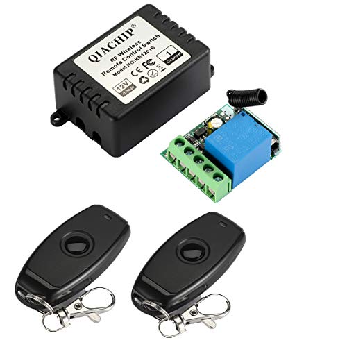
EV1527 Remote
1~4 Channel EV1527

433MHz RF EV1527 Wireless Remote

Remote Control Key Fob
The EV1527 is a very popular wireless communication RF protocol, widely used in low-cost wireless devices, such as remote-controlled garage door opener, home security systems, etc. Sometimes you can also find it in smart home devices like wireless switches and smart plugs.
This protocol transmits the data over a carrier frequency of 433.92MHz and uses amplitude-shift keying (ASK) modulation. With EV1527 protocol you can transmit up to 24 bits of data, which consists of 8-bit address code and 16-bit data. The address is used to identify the device being controlled and data to tell the device a command to execute.
One of the main advantages of the EV1527 protocol is its low power consumption, which makes it great for devices using battery power. However, because the data transmitter over the air is not encrypted and sent in plain text, it is susceptible to code grabbing.
While we are basing this post on EV1527, many similar ICs use various types of modulation and encoding schemes. Some of the ICs should work with the same instructions - EV1527 / HS1527 / FP527 / EV1528 / EV1530 / PT2240. While others might need a little bit of research, but are highly likely to be used with these instructions:
- PT2262 / PT2260 / PT2264 / HS2260 / HS2262 / SC2262 / SC2260
- HT12D / HT12E / / HT12F / HT6P20B / HT6P20D / HT6P237A / HT6P247A / HT6P437A / HT600 / HT680 / HT6207/ HT6010 / HT6012 / HT6014
- SMC918 / SMC926 / SC5262 / VD5036 / VD5326
We tried to find as many ICs that should be compatible with the provided instructions, but we did not try them ourselves. However, if you happen to have another one, that uses 315 MHz or 433 MHz communication, you might still want to give it a try.
Read the data from your existing control remote #
As mentioned earlier, the EV1527 protocol is not encrypted, which makes it perfect for us to intercept our existing remote control. Therefore, we will simply need to connect our 433 MHz receiver to the ESP32 board and read the signals from a remote control.
Let's jump right into it and see how to connect a 433 MHz RF module to ESP32. The connection is very simple and the same could be used for ESP8266 or even Arduino.
                                 +---------+
    +-------------+              |  433MHz |
    |    ESP32    |              | Receiver|
    |             |              +---------+
    |    RX       +--------------+   DATA  |
    |    GND      +--------------+   GND   |
    |    3.3V     +--------------+   VCC   |
    |             |              +---------+
    +-------------+
As you can see, you simply need to connect the 3.3V pin on the ESP32 to VCC on your 433 MHz receiver, the GND pin to the GND pin and finally RX pin on ESP32 to DATA pin on the 433 MHz receiver. Please note that in this example, we are using a 433 MHz receiver that is operated on 3.3V, which is the same as ESP32.
Next, we need to write code that would show us the read signals from remote the control in the Serial Monitor.
#include <RMT.h>

// Set the RMT channel number
#define RMT_CHANNEL 0

void setup() {
  // Initialize the RMT peripheral
  RMT.begin();

  // Set the input pin
  pinMode(RMT.rxChannelToInput(RMT_CHANNEL), INPUT);

  // Set the carrier frequency (38 kHz)
  RMT.addCarrier(RMT_CHANNEL, 38000);

  // Set the decoder
  RMT.setDecoder(RMT_CHANNEL, RMT_MODE_RX, RMT_MEM_64);

  // Enable the RMT receiver
  RMT.enableRx(RMT_CHANNEL);
}

void loop() {
  // Wait for a signal to be received
  if (RMT.getRxState(RMT_CHANNEL) == RMT_RX_ACTIVE) {
    // Get the received signal
    rmt_item32_t* items = NULL;
    uint32_t numItems = 0;
    if (RMT.read(RMT_CHANNEL, &items, &numItems) == ESP_OK) {
      // Convert the signal to a byte array
      uint8_t data[numItems / 2];
      for (int i = 0; i < numItems / 2; i++) {
        uint8_t high = items[i * 2].duration1 > items[i * 2].duration0 ? 1 : 0;
        uint8_t low = items[i * 2 + 1].duration1 > items[i * 2 + 1].duration0 ? 1 : 0;
        data[i] = (high << 1) | low;
      }

      // Print the received data
      Serial.print("Received data: ");
      for (int i = 0; i < numItems / 2; i++) {
        Serial.print(data[i], HEX);
        Serial.print(" ");
      }
      Serial.println();
    }

    // Reset the receiver
    RMT.rxReset(RMT_CHANNEL);
  }
}
In this example, we again prepare the RMT peripheral on the ESP32 board, as we did in the previous example. But in this case, we need to set the RX pin to input by using the pinMode() function, set the decoder to read mode with RMT.setDecoder() function and enable the RMT receiver by using the RMT.enableRx() function.
Next, in the loop() function we will wait for a signal to be received in the connected 433 MHz receiver by checking the RX pin state with the function RMT.getRxState(), which should return true when there is an active transmission on RX pin. Then, we will read the signal into the previously initialized rmt_item32_t buffer by using RMT.read(), convert it to a byte array and print it out in the Serial Monitor.
Finally, we will reset the RMT receiver to tell it that we are done, and waiting for the next command.
After uploading the code, open the Serial Monitor and try pressing some keys on your remote controller. If everything is set correctly, you should see the message printed in the Serial monitor that should look something like this:
Received data: FF 00 FF 00 FF 00 FF 00 FF 00 FF 00 FF 00 FF 00 FF 00 FF 00 FF 00 FF 00 FF 00 FF 00 FF 00 FF 00 FF 00 FF 00 FF 00 FF 00 FF 00 FF 00 FF 00 FF 00 FF 00 FF 00 FF 00 FF 00 FF 00 FF 00 FF 00 FF 00 FF 00 FF 00 FF 00 FF 00 FF 00 FF 00 FF 00 FF 00 FF 00 FF 00 FF 00 FF 00 FF 00 FF 00 FF 00 FF 00 FF 00 FF 00 FF 00 FF 00 FF 00 FF 00 FF 00 FF 00 FF 00 FF 00 FF 00 FF 00 FF 00 FF 00 FF 00 FF 00 FF 00 FF 00 FF 00 FF 00 FF 00 FF 00 FF 00 FF 00 FF 00 FF 00 FF 00 FF 00 FF 00 FF 00 FF 00 FF 00 FF 00 FF 00 FF 00 FF 00 FF 00 FF 00 Do this with all the buttons you have on your remote controller and save the outputs for later.
Connect ESP32 with 433MHz Transmitter #
Great! Now we have the codes from our remote controller, the only thing that's left is to use it somewhere. To begin with, we will need to see how to connect ESP32 433 MHz RF transmitter this time. You would be surprised, but the connection is almost the same, just this time we need to use the TX pin, instead of RX.
                                 +------------+
    +-------------+              |   433MHz   |
    |    ESP32    |              | Transmitter|
    |             |              +------------+
    |    TX       +--------------+   DATA     |
    |    GND      +--------------+   GND      |
    |    3.3V     +--------------+   VCC      |
    |             |              +------------+
    +-------------+
After you have connected the ESP32 with your 433 MHz transmitter, we, of course, need to write some code to transmit the previously recorded signals. This time we will need to initialize the RMT peripheral as output, and set carrier frequency and pulse length, before sending the data. You can see this in the following code.
#include <RMT.h>

// Set the RMT channel number
#define RMT_CHANNEL 0

// The hex data to send
uint8_t data[] = {0xAA, 0x55, 0x10, 0xEF};

void setup() {
  // Initialize the RMT peripheral
  RMT.begin();

  // Set the carrier frequency (38 kHz)
  RMT.addCarrier(RMT_CHANNEL, 38000);

  // Set the length of each pulse (in clock cycles)
  RMT.setCarrierLevel(RMT_CHANNEL, true, 14);
  RMT.setCarrierLevel(RMT_CHANNEL, false, 14);

  // Set the transmitter
  RMT.setCarrierMode(RMT_CHANNEL, 1, 1);
  RMT.setChannel(RMT_CHANNEL, RMT_MODE_TX, 1, 1);

  // Set the data buffer
  RMT.txBufferWrite(RMT_CHANNEL, data, sizeof(data), true);
}

void loop() {
  // Send the data repeatedly with a delay of 1 second
  RMT.txStart(RMT_CHANNEL, true);
  delay(1000);
}
So as we already did before, we need to initialize the RMT peripheral in setup() function. Also, we will need to set the length of pulses this time for submitting the data with functions RMT.setCarrierLevel() with the second parameter as true to configure the HIGH-level duration and again RMT.setCarrierLevel() but with the second parameter as false to set the LOW-level duration.
Finally, we will set the RMT as the transmitter and set signal data into the RMT buffer by using RMT.txBufferWrite().
Now that we have the ESP32 RMT set up, in the loop() we will send the data with RMT.txStart() and will wait for 1 second before we repeat the data transmission again indefinitely.
Please remember to change the uint8_t data[] = {0xAA, 0x55, 0x10, 0xEF}; with your own data that you noted earlier.
After you upload the code, the ESP32 will send your provided command every second, therefore if you have the device you were controlling with your remote control previously somewhere close enough, you should see how it executes the provided command after receiving the signal from ESP32.
Conclusions #
With all the hard work we have done, we have overviewed different 433 MHz transmitters and receivers, learned how to use RMT peripherals on ESP32 and went a little deeper with the wireless communication protocols, specifically the EV1527 protocol.
Later, we were able to read the signals of the existing remote control by using a 433 MHz receiver and putting ESP32 RMT peripheral in use to deal with the EV1527 protocol easily and could note down the signals for later use.
Finally, we reused the previously read signals and were able to execute a command on our existing wireless device.
What's next? #
So now that we have read and noted down the existing remote control signals and were able to use one of them to execute a command on an existing wireless device, the next logical step is to put all commands in place and let your mind wander freely to figure out how you will use the commands. As we have everything on ESP32, it should be fairly easy to make your device controlled with WiFi.