

Deep Sleep Low Power Optimization on ESP32 Dev Boards
Power Modes - modem sleep, deep sleep, low power peripherals and more. Optimize your ESP32 for Ultra-Low Power with strategies and real-world examples
One of the most critical considerations in IoT projects, especially those involving battery-powered applications, is power consumption.
In this blog post, we will dive into the world of ultra low power optimization on ESP32 development boards. Understanding and implementing power-saving techniques is crucial for extending battery life and enhancing the overall efficiency of your projects.
ESP32 System-on-Chip Functional Parts #
The ESP32 System-on-Chip (SoC) integrates various components, including a dual-core CPU, Wi-Fi and Bluetooth connectivity, numerous peripherals (e.g., GPIO, ADC, PWM), and an Ultra-Low Power Coprocessor (ULP). It also features security components like secure boot and flash encryption. The parts under the hood can be separated into several categories:
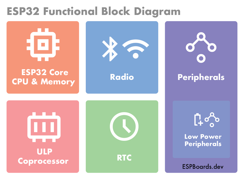
- ESP32 Core CPU & Memory: The main processor of the chip, together with memory. The key components in this part are Microprocessor, Cache, SRAM, JTAG and ROM.
- Radio: This part includes components needed for Radio Frequency (RF) communications. It includes 2.4 GHz Receiver and Transmitter, 2.4 GHz Balun + Switch, RF Synthesizer, External Main Clock, Fast RC Oscillator and Phase Lock Loop. We also include Wireless Circuits in this part, which includes WiFi and Bluetooth specific components, such as WiFi MAC, WiFi Baseband, Bluetooth LE Link Controller and Bluetooth LE Baseband.
- ULP Coprocessor: The Ultra Low Power Coprocessor is a specialized microcontroller core designed to efficiently handle low-power tasks and sensor operations while the main CPU cores are in a deep sleep state. It consists of several key components, such as ULP CPU Core, Memory, Sensor Interface, Timers, Wake-up capabilities and more.
- RTC: the Real-Time Clock provides accurate timekeeping and time-related functions. It is used to keep track of time, perform time-based operations, and schedule wake-up events. It consists of the key components, such as RTC Memory, Power Management Unit (PMU) and Brownout Detector.
- Peripherals: various hardware components and features integrated into the chip. These peripherals enhance the capabilities of the chip and allow it to interface with sensors, external devices, and more. Some of the main peripherals are UART, USB OTG, RMT, System Timer, Pulse Counter, LED PWM, LCD Interface, I2S, I2C, Camera Interface, GPIO, USB Serial/JTAG and more.
- Low Power Peripherals: you could call this as an extension to peripherals, but these are designed to work in deep-sleep mode, consuming minimal amounts of power. The key components often includes RTC GPIO, RTC ADC, eFuse Controller, RTC Watchdog Timer, Super Watchdog, Touch Sensor, Temperature Sensor, etc.
Understanding ESP32 Power Modes #
ESP32 development boards offer multiple power modes, each with its unique characteristics and implications on power consumption. To achieve ultra-low power operation, it's crucial to understand these modes thoroughly.
- Active Mode
This is the standard operating mode when the ESP32 is actively executing code. While it provides the highest processing power, it also consumes the most energy.
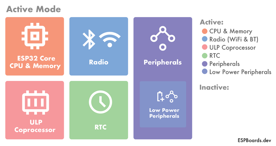
All the parts of ESP32 SoC are active in this mode. To optimize power in this mode, consider using efficient algorithms and minimizing unnecessary computations.
- Modem Sleep (ESP 32 Light Sleep)
ESP32 Light sleep or sometimes called Modem Sleep is ideal when you don't need to utilize Radio Communications or need to conserve power while waiting for external events, such as sensor inputs.
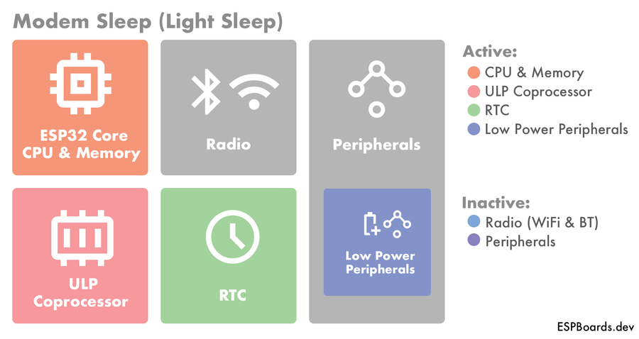
In ESP32 Light Sleep mode, the Radio is shut down, meaning there are no RF capabilities in this mode. Most of the peripherals are also off, excluding the Low Power Peripherals. By configuring wake-up sources intelligently, you can significantly reduce energy consumption.
- Deep Sleep
Among the most power-efficient modes in ESP32, deep sleep turns off the main ESP32 Core, which includes main processing power and memory, resulting in minimal power usage.
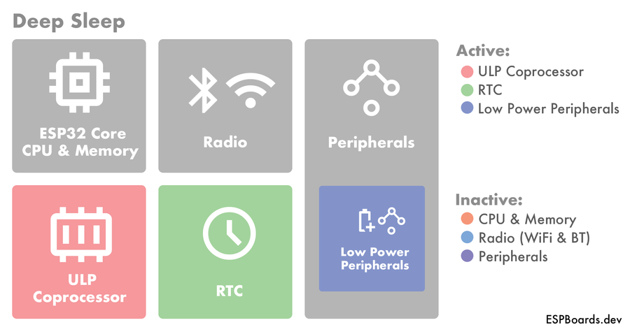
While the ESP32 Core is shut down, the ULP Coprocessor stays active and waits for an external trigger or timer to wake up from deep sleep. Properly configuring deep sleep is crucial for maximizing energy savings, especially in scenarios where the ESP32 is periodically collecting data or sending intermittent updates.
- Hibernation
This is the most power-conservative mode. It's useful for ultra-low power applications with long sleep periods, such as remote sensor nodes running on batteries.
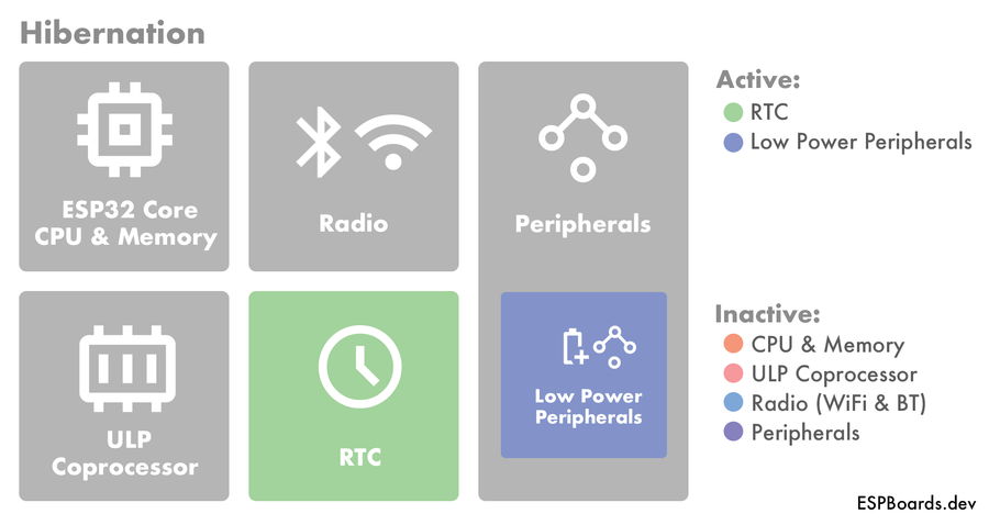
In this mode, almost all internal circuits, except for the RTC (Real-Time Clock) are shut down, meaning there isn't really enough space for processing anything, but it still handles the wake-up timers or triggers.
ESP32 Power Modes Overview #
By choosing the appropriate power mode and optimizing code execution, you can strike the right balance between performance and energy efficiency for your ESP32 projects. In the following sections, we'll explore specific power optimization techniques to get the most out of each power mode.
Power Optimization Techniques: Enhancing Energy Efficiency #
To achieve optimal power consumption on ESP32 development boards, a combination of software and hardware techniques can be employed. Let's explore some effective power optimization strategies:
Efficient Sleep Periods and Modes: Fine-tune the sleep periods based on the application's requirements. Minimize wake-ups and maximize sleep times to strike the right balance between responsiveness and power conservation. Choose the appropriate wake-up sources for each power mode. Select sensors and triggers that consume minimal power while still providing the necessary functionality. Make sure to shut down as many unused components as possible.
Clock Management and Dynamic Frequency Scaling: Adjusting the system clock frequency can significantly impact power usage. Lowering the CPU clock during periods of low activity reduces power consumption while still maintaining functionality. Be cautious when adjusting clock speeds though, as it may affect the timing accuracy of time-sensitive operations.
Low-Power Peripherals: Utilize esp32 low power versions of peripherals whenever possible. For instance, the ESP32 offers ULP (Ultra-Low Power) coprocessor that can handle specific tasks without waking up the main CPU, conserving energy during light sleep and deep sleep modes.
Task Scheduling: Organize tasks effectively and avoid unnecessary background processes during sleep modes. Properly manage the task scheduler to ensure that tasks run only when needed, minimizing power consumption.
Power Supply Considerations: Choose efficient power supply components and circuit designs to minimize power losses. Use low-dropout regulators and power-saving features on voltage regulators when available.
Verify with a multimeter: Use a multimeter with µA resolution to measure your actual deep-sleep current draw. If you're seeing milliamps instead of microamps, something isn't sleeping - see our multimeter buying guide for meters with µA range.
By implementing these power optimization techniques with care, you can transform your ESP32 projects into highly energy-efficient solutions, ideal for battery-powered and energy-conscious applications. In the next section, we'll go through these techniques in practical examples and case studies to illustrate the benefits of ultra-low power optimization on ESP32 development boards.
Implementation: Practical Guide to Ultra-Low Power Optimization #
Now that we know quite a bit about power optimization on ESP32 chips, let's put it in practice. We will go through different techniques in separate examples. Keep in mind all of the provided techniques can be merged into one efficient ultra low power application.
- ESP32 Disable WiFi and Bluetooth
The most common use case to save power in ESP32, is to disable the WiFi or / and Bluetooth, if they are not being used. Even though if the WiFi or Bluetooth is not initialised, it is turned off by default. However, you might want to disable/enable WiFi and Bluetooth on ESP32 periodically in you program.
#include "WiFi.h"

#define WIFI_SSID "your-ssid"
#define WIFI_PW "your-pass"

void setup() {
    Serial.begin(115200);

    // --- Enable / disable Bluetooth ---
    // Start Bluetooth
    Serial.println("Starting Bluetooth");
    btStart();
    delay(5000);

    // Stop Bluetooth
    Serial.println("Stopping Bluetooth");
    btStop();
    delay(5000);
    // --- ---

    // --- Enable / disable WiFi ---
    // Start WiFi in Station (STA) Mode
    Serial.println("Starting WiFi in Station Mode");
    WiFi.begin(WIFI_SSID, WIFI_PW);
    delay(5000);

    // Disable WiFi
    Serial.println("Stopping WiFi");
    WiFi.mode(WIFI_OFF);
    delay(5000);
    // --- ---

    // --- Enable / Disable Both WiFi and Bluetooth
    // Enable WiFi and Bluetooth
    Serial.println("Starting Both WiFi and Bluetooth");
    btStart();
    WiFi.begin(WIFI_SSID, WIFI_PW);
    delay(5000);

    // Disable WiFi and Bluetooth
    Serial.println("Stopping Both WiFi and Bluetooth");
    WiFi.mode(WIFI_OFF);
    btStop();
    delay(5000);
    // --- ---
}

void loop() {

}
In the example above, when you turn on the ESP32, it will enable Bluetooth and disable it after 5 seconds. Then it will enable and connect to WiFi and disable the WiFi after 5 seconds. Finally it will enable both Bluetooth and WiFi again, and after 5 seconds delay, it will disable ESP32 WiFi and Bluetooth.
- Configuring Power Modes and Wakup Sources
Next, we will take a look at how to utilize different power modes (light sleep, deep sleep, and hibernation). To be able to continue the ESP32 operation in normal mode after a sleep, we need to configure a wake-up source.
There are multiple different options to use for a wake-up source, the easiest being a timer, which simply wakes up after a specified amount of time. However, that might not always be suitable for specific applications. Let's take a look at other wake-up sources first:
- Touch Sensor Wake-up: Some ESP32 modules include touch sensors that can be used to wake up the device when touched or when a change in capacitance is detected
- External Wake-up: the ESP32 can be awakened from deep sleep by an external signal on a designated RTC GPIO pin.
- ULP Coprocessor Wake-up: The ULP coprocessor can wake up the ESP32 when certain conditions are met, such as a sensor threshold being crossed.
- GPIO Wake-up (Only from Light Sleep Mode): GPIO pins can be configured to trigger a wake-up when their state changes, such as a button press.
- UART Wake-up (Only from Light Sleep Mode): UART Wake-up is similar to GPIO Wakeup but specific to UART communication
For the simplicity of examples, we will show how to use different Sleep Modes on ESP32, using the Timer wake-up source.
const uint32_t SLEEP_DURATION = 5 * 1000000; // µs

// ESP32 boot count
RTC_DATA_ATTR int bootCount = 0;

void printWakeUpReason() {
  esp_sleep_wakeup_cause_t wakeupReason = esp_sleep_get_wakeup_cause();

  switch (wakeupReason) {
    case ESP_SLEEP_WAKEUP_EXT0:
      Serial.println("The device was awakened by an external signal using RTC_IO.");
      break;
    case ESP_SLEEP_WAKEUP_EXT1:
      Serial.println("The device was awakened by an external signal using RTC_CNTL.");
      break;
    case ESP_SLEEP_WAKEUP_TIMER:
      Serial.println("The device was awakened by a timer event.");
      break;
    case ESP_SLEEP_WAKEUP_TOUCHPAD:
      Serial.println("The device was awakened by a touchpad interaction.");
      break;
    case ESP_SLEEP_WAKEUP_ULP:
      Serial.println("The device was awakened by a ULP (Ultra-Low-Power) program.");
      break;
    default:
      Serial.printf("The device woke up for an unknown reason: %d\n", wakeupReason);
      break;
  }
}

void setup() {
  Serial.begin(115200);
  delay(1000); // Wait a bit to make sure Serial starts

  // Print boot counter every boot
  ++bootCount;
  Serial.println("Boot number: " + String(bootCount));

  // Print wake up reason
  printWakeUpReason();
}

// Enter Light Sleep with Timer Wake-up source
void lightSleep() {
    esp_sleep_enable_timer_wakeup(SLEEP_DURATION);
    esp_light_sleep_start();
}

// Enter Deep Sleep with Timer Wake-up source
void deepSleep() {
    esp_sleep_enable_timer_wakeup(SLEEP_DURATION);
    esp_deep_sleep_start();
}

// Enter Hibernation mode with Timer Wake-up source
void hibernate() {
    // Shut down RTC (Low Power) Peripherals
    esp_sleep_pd_config(ESP_PD_DOMAIN_RTC_PERIPH,   ESP_PD_OPTION_OFF);
    // Shut down RTC Slow Memory
    esp_sleep_pd_config(ESP_PD_DOMAIN_RTC_SLOW_MEM, ESP_PD_OPTION_OFF);
    // Shut down RTC Fast Memory
    esp_sleep_pd_config(ESP_PD_DOMAIN_RTC_FAST_MEM, ESP_PD_OPTION_OFF);
    // Shut down Crystal Oscillator XTAL
    esp_sleep_pd_config(ESP_PD_DOMAIN_XTAL,         ESP_PD_OPTION_OFF);
    // Enter Deep Sleep
    deepSleep();
}

void loop() {
  Serial.println("Entering Light Sleep mode...");
  delay(1000);
  lightSleep();

  Serial.println("Entering Deep Sleep mode...");
  delay(1000);
  deepSleep();

  Serial.println("Entering Hibernation mode...");
  delay(1000);
  hibernate();
}
This application should print the incrementing boot count, tell the reason of wake-up, write the mode ESP32 will enter next to the Serial Monitor and go into Deep / Light Sleep or Hibernation mode.
Use this template in your application to utilize the different power modes ESP32 provides.
- Setting CPU Frequency
On ESP32, you can set the CPU frequency in the runtime easily. You can do that to reduce the power consumption in the parts of the application that doesn't need much processing power.
The supported CPU frequencies are 240 MHz, 160 MHz, and 80 MHz. If the XTAL (crystal oscillator) frequency is less than 40 MHz, additional frequencies of 40 MHz and 20 MHz are supported.
void setup() {
  Serial.begin(115200);
  Serial.printf("XTAL Frequency: %i MHz", getXtalFrequencyMhz());
  Serial.printf("APB Frequency: %i MHz", getApbFrequency());
}

void loop() {
  Serial.printf("CPU Frequency: %i MHz", getCpuFrequencyMhz());

  setCpuFrequencyMhz(160);
  delay(2000);
  Serial.printf("CPU Frequency: %i MHz", getCpuFrequencyMhz());

  setCpuFrequencyMhz(80);
  delay(2000);
}
The code above will print the XTAL and APB Frequencies on boot. First, it will print the current CPU frequency. Next, it will set the CPU frequency to 160 MHz, wait for 2 seconds and print the actual CPU frequency, which should be 160 MHz now. Finally, it will set the CPU frequency to 80 MHz and print it after 2 seconds and it will repeat indefinitely.
- ESP32 Low-Power Peripherals: Utilize ULP coprocessor for specific tasks without waking up the main CPU.
The ESP32 microcontroller provides RTC GPIO support, which enables the use of specific GPIO pins in the RTC low-power subsystem during deep sleep. These designated RTC GPIOs serve as wake-up sources, allowing the ESP32 to be awakened from deep sleep, especially when the Ultra Low Power (ULP) co-processor is active. These GPIO pins can be configured to trigger the wake-up process, making them valuable for resuming operation after low-power states.
In the deep sleep mode, specific ESP32 pins are available for utilization by the ULP co-processor, including the RTC_GPIO pins and the Touch Pins. You can find a comprehensive list of RTC_GPIO pins in the ESP32 datasheet.
- Efficient Task Scheduling
Organize tasks and use deep sleep to ensure only essential processes run when needed.
#include <Arduino.h>
#include <esp_sleep.h>

void mainTask() {
  // Mock Main Task code
  delay(500);
}

void secondaryTask() {
  // Mock Secondary Task code
  delay(1000);
}

void setup() {
  // Add your setup code here
}

void loop() {
  // Calculate the time until the next scheduled task or event
  unsigned long nextMainTaskTime = millis() + 500;
  unsigned long nextSecondaryTaskTime = millis() + 1000;

  // Determine the minimum time until the next task
  unsigned long nextTaskTime = min(nextMainTaskTime, nextSecondaryTaskTime);

  // Enter deep sleep to save power until the next task is scheduled
  esp_sleep_enable_timer_wakeup(nextTaskTime * 1000); // Convert to microseconds
  esp_deep_sleep_start();
}
This Arduino code defines two mock tasks with specific delays, calculates the time until the next task is scheduled, and enters deep sleep mode on an ESP32 to save power until that time. It effectively waits for the soonest of the two tasks to occur and minimizes power consumption during the idle period.
- Battery Management: Implement techniques to monitor battery levels and extend battery life.
#include <Arduino.h>

// Analog pin used for reading battery voltage
const int BATTERY_PIN = A0;

// Function to read battery voltage
float readBatteryVoltage() {
  int rawValue = analogRead(BATTERY_PIN);
  float voltage = rawValue * (3.3 / 1023.0);  // Convert ADC reading to voltage
  return voltage;
}

void setup() {
  // Add your setup code here
}

void loop() {
  // Read the current battery voltage
  float batteryVoltage = readBatteryVoltage();

  // Implement battery management logic based on batteryVoltage
  if (batteryVoltage < 3.0) {
    // Take actions to extend battery life, such as reducing power-hungry operations
    // Implement deep sleep, adjust performance, or send a low battery alert
  }

  // Your main code for regular operation here
}
This Arduino code reads the voltage of a battery connected to an analog pin and performs battery management based on the voltage level. It converts the analog reading to voltage and checks if the battery voltage is below 3.0 volts. If it's low, it suggests taking actions to preserve battery life, like entering deep sleep mode, adjusting performance, or sending a low battery alert. This code is essential for managing power resources when running applications on battery-powered devices.
Case Studies: Implementing Ultra-Low Power on ESP32 Development Boards #
Let's explore some real-world examples of how ultra-low power optimization can be applied to ESP32 projects:
Wireless Sensor Network (WSN): Imagine you're designing a wireless sensor network to monitor environmental conditions in a remote location. By implementing proper power management techniques, you can ensure the ESP32 nodes sleep most of the time, waking up periodically to collect and transmit data. Utilizing deep sleep mode along with efficient wake-up triggers, such as timed intervals or external events, can lead to prolonged battery life, enabling long-term, autonomous operation.
Battery-Powered IoT Device: Consider a battery-powered IoT device, like a smart door sensor or a wearable fitness tracker, where energy efficiency is crucial for extended usage. By optimizing the ESP32's power modes and fine-tuning sleep durations, you can strike a balance between responsiveness and power consumption. For example, using light sleep mode with sensor wake-up capabilities can maintain timely data updates while still conserving energy during idle periods.
Remote Monitoring Station: In applications where power sources are scarce or inaccessible, such as remote weather monitoring stations or wildlife tracking devices, hibernation mode can be a game-changer. By shutting down non-essential components and relying on the RTC to wake up the ESP32 at specific intervals, you can achieve ultra-low power operation for months or even years without battery replacements.
These case studies demonstrate the actual benefits of optimizing power consumption on ESP32 development boards. Depending on your project's specific requirements, you can choose from a range of power modes and techniques to achieve energy-efficient and sustainable solutions.
Conclusion: Unlocking Energy Efficiency with ESP32 #
In this blog post, we've explored the ESP32 SoC in more detail, looking at the different parts the chip consists of. We have then explored the different ESP32 Power Modes and learned which parts are getting shut down in different modes.
We have then further explored why should we consider power consumption in microcontroller projects and what other strategies we can utilize, apart different power modes, to save power.
Finally, we have utilized the different power saving strategies with code examples, which can be used in your projects as a template.