
ESP32 RGB LED Controller with Color Picker over WebSockets
Step by step guide on building the RGB LED Color Picker controller on ESP32 microcontroller. Interactive and responsive website application with WebSockets
With the built-in WiFi module in the ESP32, it gives a great opportunity to make a Web Controller RGB LED.
We don't want to provide RGB values every time we want to change the color. Instead, we want a nice, interactive interface to do the job.
To achieve this, we will need to make a decent-looking web interface. For a beautiful color control, we will be using the iro.js library - a color picker widget for JavaScript. And to make everything interactive, we will make use of Web Sockets by running the WebSockets Server and serving the website on ESP WebServer with WebSockets Client on ESP32.
In case you want to see the final result, jump to Control the RGB LED with the color picker where you can see the video in action.
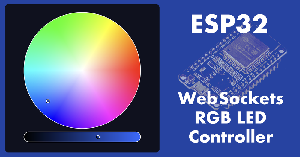
Table of Contents #
- Table of Contents
- Create a layout for our Website with Color Picker
- Download the iro.js color picker widget
- Initialize the Color Picker Widget
- Use the color picker
- Create a WebServer with WebSockets on ESP32
- Connect the RGB LED to the ESP32
- Create the Web Socket client
- Full code example
- Upload the application and website to ESP32
- Control the RGB LED with the color picker
- Conclusion and next steps
Create a layout for our Website with Color Picker #
As we are going to use the color picker widget already, we are aiming for the website to look nice. Therefore, we will first build the website layout.
1. Create the project directory #
To begin with, create a new folder with your project name. We will name it ESPWebSocket and create a data folder inside. The folder structure should be like the following:
- ESPWebSocket (Arduino Project Root)
- data
2. Create an HTML structure #
To create a website layout for the website, we first need to define the HTML that will have an element to hold a color picker. Inside the data folder, create a file called index.html and add the following contents:
<!DOCTYPE html>
<head>
<title>ESP32 WebSocket Color Picker</title>
<link rel="stylesheet" href="css/main.css">
</head>
<body>
<div class="container">
<div class="content">
<div id="color" class="picker">Color Picker will be here</div>
</div>
</div>
</body>
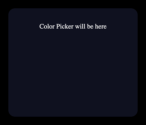
</html>3. Add some styles #
If you would open the website now, all you would see is an empty space. Don't worry, that is expected, but not what we actually want. To achieve the actual structure we want, we will add some CSS styles next. Inside a data folder again, create a new folder, called css and inside, create a file called main.css, with the following content:
    :root {
        --picker-width: 800px;
    }

    body, html {
        height: 100%;
        width: 100%;
        margin: 0;
        background: black;
        color: white;
        overflow: hidden;
    }

    .container {
        min-height: calc(100% - 2 * 20px);
        margin: 20px;
        background: #0f111f;
        border-radius: 16px;
        text-align: center;
    }

    .content {
        padding: 35px 50px;
    }

    .picker {
        max-width: var(--picker-width);
        margin: auto;
    }
At this point, your file structure should look like this:
- ESPWebSocket (Arduino Project Root)
- data
- css
- main.css
- index.html
- css
- data
With the index.html and main.css filled in, we should have a simple responsive structure with a placeholder for the color picker.
Download the iro.js color picker widget #
The website with the color picker widget will be living inside the ESP32. It is a great idea to consider, that we might not always have internet access on the ESP32 and will be using the application inside the LAN network only. Therefore, the CDN option is not feasible for us and we will need to store the iro.js library in ESP32, together with our website.
- Inside the
datafolder, create a new folder namedjs - Go to the official iro.js getting started guide and download the Production version.
- Place the downloaded
iro.min.jsfile inside thejsfolder. - Load this javascript from the HTML. Inside the
index.html, below the line<link rel="stylesheet" href="css/main.css">, insert a new line a put this code:<script src="js/iro.min.js"></script>.
At this point, your project's folder structure should look like this:
- ESPWebSocket (Arduino Project Root)
- data
- css
- main.css
- js
- iro.min.js
- index.html
- css
- data
Initialize the Color Picker Widget #
Next, we will replace the color picker placeholder with the actual color picker. To do this, we will need to initialize the iro.js widget and provide the html element id for it.
Inside the previously created
jsfolder, create a new file, callediro_picker.js. Next, we will fill this file with some JavaScript.Create a function to get the color picker width, that we set previously inside the css.
function getPickerWidth() {
    const root = document.querySelector(':root');
    const rootStyle = getComputedStyle(root);
    return Number(rootStyle.getPropertyValue('--picker-width').replace("px", ""));
}

const pickerWidth = getPickerWidth();
This will help us manage the size of the color picker. In case you want to make the color picker bigger or smaller, you will need to replace the size in one place only - inside the css/main.css, :root { --picker-width: 800px; } - replace 800px with whatever width you want your color picker to be.
- Initialize the iro.js color picker Finally, we can place the color picker on our website. To do this, we will initialize the iro.js widget and provide the HTML element on which the color picker should appear.
const colorPicker = new iro.ColorPicker('#color', {
    width: pickerWidth,
    color: "rgb(255, 0, 0)",
    borderWidth: 2,
    borderColor: "#fff",
    wheelLightness: false,
    sliderSize: pickerWidth / 11,
});
colorPicker.color.value = 0; // Initially the LED is off
Here, we create a new object, using the iro.js library by calling the new iro.ColorPicker(). For the first parameter, we provide the HTML element with id='color', which we created earlier in the HTML layout. The second parameter is the object for color picker configuration. For example, we provide the color: "rgb(255, 0, 0)" to set the initial color to red.
By default, as we have provided rgb(255, 0, 0), the iro.js interprets this as a red color with 100% brightness. However, when we first open the website, probably the LED will be off (0% brightness), therefore we set the color.value to 0.
Execute this JavaScript code. Finally, we have a code to initialize the color picker, but we are not executing this code anywhere yet. To execute the code, we need to place this javascript in the previously defined HTML structure. In
index.html, below the line<script src="js/iro.js"></script>, insert a new line and paste this code:<script src="js/iro_picker.js"></script>.Also, we can now remove the text "Color Picker will be here" and keep that line with
<div id="color" class="picker"></div>
You should have 3 files in total now in the following folder structure:
- ESPWebSocket (Arduino Project Root)
- data
- css
- main.css
- js
- iro.min.js
- iro_picker.js
- index.html
- css
- data
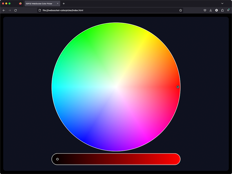
And the website, when opening the index.html file inside the browser, should look like this
Use the color picker #
Finally, we have the website with the color picker. But it is not doing much at the moment... Let's add some logic for the color picker.
- Inside the iro_picker.js, attach the javascript event
input:changefrom iro.js picker
colorPicker.on('input:change', function(value) {
    console.log(value.rgb);
});
Whenever the color picker value changes, it will call this function, which in turn will print the RGB color value to the console.
- Debounce the color picker input Note, that every small change in the color picker, will call this function. In case we drag the mouse to change the color, it will call the previously defined function. This will result in multiple prints to the console. While this is fine for printing the value in the console, it would overwhelm the network and ESP32 with that many requests.
In order to fix this, we need to delay the processing of the function, by setting the timeout. Change the previously defined function to the following:
let debounce = null;
colorPicker.on('input:change', function(value) {
    if (!debounce) {
        console.log(value.rgb);
    }
    debounce = setTimeout(() => {
        debounce = undefined;
    }, 100);
});
This change will prevent processing the function instantaneously, and instead, it will only do so every 100 milliseconds. If you find this to be a bit jerky, reduce the 100 to a smaller number.
- (Optional) Change Background Color according to Color Picker
To make our website feel more interactive, we can change the background color, whenever the color in the color picker changes. To do so, we will define a function changeBackgroundColor() inside the ino_picker.js:
function changeBackgroundColor(rgb) {
    document.body.style.backgroundColor = "rgb(" + rgb.r + ", " + rgb.g + ", " + rgb.b + ")";
}
And we will use this function on the input:change event. Replace the previously defined function colorPicker.on(), to the following:
let debounce = null;
colorPicker.on('input:change', function(value) {
    if (!debounce) {
        console.log(value.rgb);
        changeBackgroundColor(value.rgb);
    }
    debounce = setTimeout(() => {
        debounce = undefined;
    }, 100);
});
And finally, we have the website with the color picker ready. We can select a color and it will be reflected on the background. Also, we print the RGB values to the console and we will use these values to control the RGB LED connected to the ESP32.

Create a WebServer with WebSockets on ESP32 #
Now that we have the website with the color picker ready, we can put it aside for a bit and move to the more interesting part - programming the ESP32.
1. Install libraries #
Before you begin with this step, make sure you have the required libraries installed:
2. Create Folder Structure #
After making sure you have the libraries, for the Web Socket server on ESP32, we will need several things:
- WiFi connection
- Web Server
- Web Socket server
Keeping this in mind, create the missing files in the following structure. The final folder structure should look like this:
- ESPWebSocket (Arduino Project Root)
- ESPWebSocket.ino
- WiFi.h
- WebServer.h
- WebServer.cpp
- WebSocket.h
- WebSocket.cpp
- RGBLed.h
- RGBLed.cpp
- data
- css
- main.css
- js
- iro.min.js
- iro_picker.js
- index.html
- css
3. Fill in the logic #
- Fill in the
WiFi.hWe will start by initializing the WiFi module and connecting to the WiFi network.
Put the following code in WiFi.h file:
#ifndef WIFI_H
#define WIFI_H

#include <WiFi.h>

#define WIFI_SSID     "YOUR_WIFI_SSID"
#define WIFI_PASSWORD "YOUR_WIFI_PASSWORD"

// Init WiFi
void initWiFi() {
  WiFi.mode(WIFI_STA);
  WiFi.begin(WIFI_SSID, WIFI_PASSWORD);
  Serial.print("Connecting to WiFi ..");
  while (WiFi.status() != WL_CONNECTED) {
      Serial.print('.');
      delay(1000);
  }
  Serial.println(WiFi.localIP());
}

#endif
Make sure to replace the YOUR_WIFI_SSID and YOUR_WIFI_PASSWORD with your WiFi network credentials.
This will connect your ESP32 board to the provided WiFi network and will print the IP address to Serial Monitor.
- Fill in the
WebServer.h
In order to be able to open the website, which we created earlier, that will be inside the ESP32, we need a Web Server.
Put the following code in WebServer.h file:
#ifndef WEB_SERVER_H
#define WEB_SERVER_H

#include "LittleFS.h"
#include <AsyncTCP.h>
#include <ESPAsyncWebServer.h>

String processor(const String& var);

// Setup WebServer routes
void setupRoutes();

// Initialize LittleFS
void initLittleFS();

void setupWebServer();

#endif
and the WebServer.cpp file:
#include "WebServer.h"
#include "WebSocket.h"
#include <ArduinoJson.h>

AsyncWebServer server(80);

String processor(const String& var) {
  if(var == "WEB_SERVER_IP") {
    return WiFi.localIP().toString();
  }
  return String();
}

// Setup WebServer routes
void setupRoutes() {
  server.on("/", HTTP_GET, [](AsyncWebServerRequest *request){
    request->send(LittleFS, "/index.html", String(), false, processor);
  });
}

// Initialize LittleFS
void initLittleFS() {
  if (!LittleFS.begin()) {
    Serial.println("An error has occurred while mounting LittleFS");
  }
  Serial.println("LittleFS mounted successfully");
}

void setupWebServer() {
  initLittleFS();
  setupRoutes();
  server.serveStatic("/", LittleFS, "/");
  server.begin();
  server.addHandler(&ws);
}
This code will mount the LittleFS and when you open the root of the web server (/), it will serve the index.html from the filesystem (LittleFS).
Also, when serving the index.html, we defined that before responding with the contents, we would use the function processor(), which will replace the string %WEB_SERVER_IP% in our index.html file, with the actual ESP32 IP address.
- Fill in the WebSocket.h
Next, we will initialize the Web Socket server, to be able to have continuous communication between all the connected clients.
First, let's define the function names. Put the following code inside the WebSocket.h file:
#include <ArduinoJson.h>
#include "RGBLed.h"
#include "WebServer.h"

extern AsyncWebSocket ws;

void notifyClients(int r, int g, int b);

void handleCommand(DynamicJsonDocument json);

void handleWebSocketMessage(void *arg, uint8_t *data, size_t len);

void onSocketEvent(AsyncWebSocket *server, AsyncWebSocketClient *client,AwsEventType type,
             void *arg, uint8_t *data, size_t len);

void initWebSocket();
And second, let's put the logic for the defined functions. Put the following code inside the WebSocket.cpp file:
#include "WebSocket.h"

AsyncWebSocket ws("/ws");

void notifyClients(int r, int g, int b) {
    const uint8_t size = JSON_OBJECT_SIZE(8);
    StaticJsonDocument<size> json;
    json["status"] = "ok";
    json["r"] = r;
    json["g"] = g;
    json["b"] = b;

    char data[400];
    size_t len = serializeJson(json, data);
    ws.textAll(data, len);
}

void handleCommand(DynamicJsonDocument json) {
  const char* action = json["action"];
  Serial.println(action);

  if ((strcmp(action, "change") == 0)) {
    const int r = json["data"]["r"];
    const int g = json["data"]["g"];
    const int b = json["data"]["b"];
    writeRGBLed(r, g, b);
    notifyClients(r, g, b);
  } else if ((strcmp(action, "init") == 0)) {
    notifyClients(0, 0, 0);
  }
}

void handleWebSocketMessage(void *arg, uint8_t *data, size_t len) {
  AwsFrameInfo *info = (AwsFrameInfo*)arg;
  if (info->final && info->index == 0 && info->len == len && info->opcode == WS_TEXT) {

    DynamicJsonDocument json(2048);
    DeserializationError err = deserializeJson(json, data);
    if (err) {
      Serial.print(F("deserializeJson() failed with code "));
      Serial.println(err.c_str());
      return;
    }

    handleCommand(json);
  }
}

void onSocketEvent(AsyncWebSocket *server, AsyncWebSocketClient *client,AwsEventType type,
             void *arg, uint8_t *data, size_t len) {
  switch (type) {
    case WS_EVT_CONNECT:
      Serial.printf("WebSocket client #%u connected from %s\n", client->id(), client->remoteIP().toString().c_str());
      break;
    case WS_EVT_DISCONNECT:
      Serial.printf("WebSocket client #%u disconnected\n", client->id());
      break;
    case WS_EVT_DATA:
      handleWebSocketMessage(arg, data, len);
      break;
    case WS_EVT_PONG:
    case WS_EVT_ERROR:
      break;
  }
}

void initWebSocket() {
    ws.onEvent(onSocketEvent);
    Serial.println("Websocket started");
}
First, we initialize the web socket server with AsyncWebSocket ws("/ws") and by calling the initWebSocket() function. For the initWebSocket() function, we need to have a callback function, that will be called whenever the web socket receives an event. We define this callback with onSocketEvent() function.
Whenever we receive data (WS_EVT_DATA event), we will call a function handleWebSocketMessage(), which will deserialize the JSON with deserializeJson() function from the ArduinoJson library. When we have the data inside the object, we will call a function handleCommand().
The handleCommand() function will check for the action, and in case it is change, it will set the RGB LED color. After the action is processed, we will call the notifyClients() function, which will send a response to the Website, so we can adjust the color picker value on all the clients.
- Define the RGB LED
Fill in the RGBLed.h file with the following contents:
#ifndef RGB_LED_H
#define RGB_LED_H

#include "Arduino.h"

const int LED_R = 18; // GPIO
const int LED_G = 5; // GPIO
const int LED_B = 4; // GPIO

void initRGBLed();

void writeRGBLed(int r, int g, int b);

#endif
Make sure to replace the LED_R, LED_G and LED_B values with the ESP32 GPIO pins, where you will connect the RGB LED.
And fill in the RGBLed.cpp file with the following"
#include "RGBLed.h"

void initRGBLed() {
  pinMode(LED_R, OUTPUT);
  pinMode(LED_G, OUTPUT);
  pinMode(LED_B, OUTPUT);
}

void writeRGBLed(int r, int g, int b) {
  analogWrite(LED_R, r);
  analogWrite(LED_G, g);
  analogWrite(LED_B, b);
}
In this file, we will define the LED_R, LED_G and LED_B pins as OUTPUT in the initRGBLed() function. And will declare the function writeRGBLed(), which will take 3 parameters for Red, Green and Blue colors values and will write the values to RGB Led connected pins.
- Fill in the main logic in ESPWebSocket.ino
Now that we have all the logic ready for the WiFi connection, Web Server and Web Socket server, we will use it in the main application.
Put the following code inside the ESPWebSocket.ino file:
#include "WiFiController.h"
#include "RGBLed.h"
#include "WebSocket.h"
#include "WebServer.h"

void setup() {
    Serial.begin(115200);
    delay(10);

    initRGBLed(); // RGBLed.h
    initWiFi(); // WiFi.h
    initWebSocket(); // WebSocket.h
    setupWebServer(); // WebServer.h
}

void loop() {
  ws.cleanupClients();
}
First, we include the other files we created earlier. Next, initialize the Serial port to be able to see the logs and debug our application with the Serial monitor. Next, we will call functions initRGBLed from the RGBLed.h file, initWiFi() from the WiFiController.h file, initWebSocket() from the WebSocket.h file and initWebServer() from the WebServer.h.
Finally, we loop the ws.cleanupClients() to clean up the web socket server after the client disconnects from the server.
Connect the RGB LED to the ESP32 #
Connect your ESP32 with the RGB LED, as shown in the picture below.
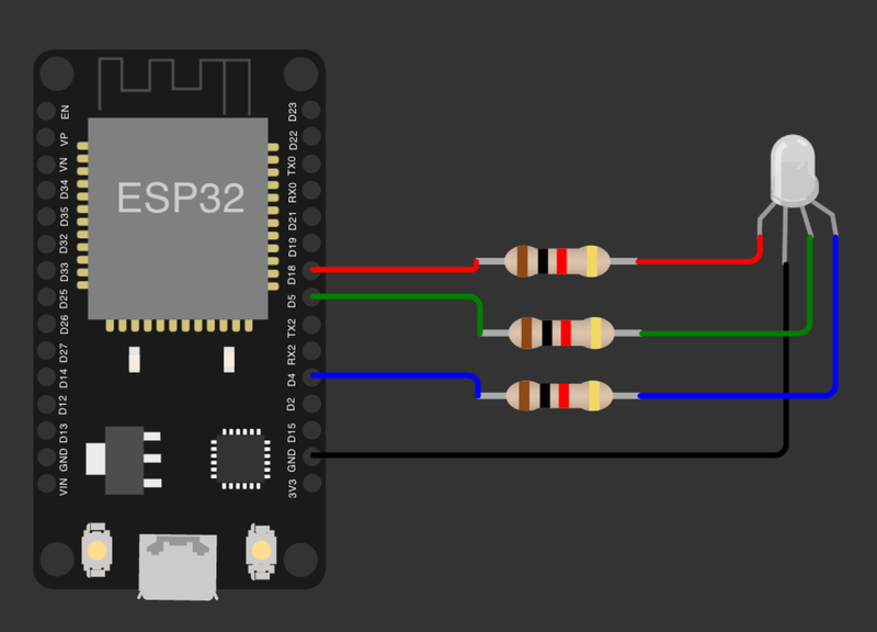
Position the RGB LED, so the longest LED leg is the second from the left - this will be the GND pin. Then on the left side, you have the RED pin, and on the right side from the GND pin are the GREEN and BLUE pins respectively.
Connect the GND to GND pin on the ESP32, RED, GREEN and BLUE pins to the GPIO pins on ESP32 through the resistors. Make sure to use the resistors, in order not to damage the LED. We used 220 Ohm value resistors.
Create the Web Socket client #
Now that we have the front-end (Color Picker website application) and the back-end (ESP32 application with Web Sockets server), we need to connect them together. The code on the ESP32 side to handle the command from WebSocket is already done and we need to come back to the website side.
1. Web Socket client logic #
In the data/js/ folder, create a new file named socket.js and fill in the following code in
let socket = new WebSocket(WEBSOCKET_ADDRESS);

socket.onopen = function(e) {
  console.log("[open] Connection established");
  console.log("Sending to server");
  socket.send("{ 'action': 'init' }");
};

socket.onmessage = function(event) {
  let data = JSON.parse(event.data);

  colorPicker.color.red = data.r;
  colorPicker.color.green = data.g;
  colorPicker.color.blue = data.b;
  changeBackgroundColor(data);

  console.log(`[message] Data received from server: ${event.data}`);
};

socket.onclose = function(event) {
  if (event.wasClean) {
    console.log(`[close] Connection closed cleanly, code=${event.code} reason=${event.reason}`);
  } else {
    console.log('[close] Connection died');
  }
};

socket.onerror = function(error) {
  console.log(`[error]`);
};
First, we will declare a new WebSocket object, by providing the ESP32 IP address (We will show how to get this address in the next section).
When the client opens a website, socket.onopen function will be called, which will log connection success to the console and send the init action to the ESP32 Web Socket server. The ESP32 will respond with the current LED value and in this way, we will keep all the clients synchronized on the initial website load.
Next, we will define the socket.onmesage function, which will be called every time the website receives a message from the Web Socket and will set the color picker value accordingly.
We also will define the function socket.onclose to log to the console, when the web socket connection closes.
In case the error happens, socket.onerror function will be called.
2. Use the Web Socket client #
Now that we have the logic for the web socket client, we need to use it. Open the index.html file and replace the code to the following:
<!DOCTYPE html>
    <head>
        <title>ESP32 WebSocket Color Picker</title>
        <link rel="stylesheet" href="css/main.css">
        <script src="js/iro.min.js"></script>
        <script src="js/iro_picker.js"></script>
        <script>
            const WEB_SERVER_IP = '%WEB_SERVER_IP%';
            const WEBSOCKET_ADDRESS = 'ws://' + WEB_SERVER_IP + '/ws';
        </script>
        <script src="js/socket.js"></script>
    </head>
    <body>
        <div class="container">
            <div class="content">
                <div id="color" class="picker"></div>
            </div>
        </div>
    </body>
</html>
We have added a few lines to the previous index.html version. First, we defined the websocket server address with these lines
<script>
    const WEB_SERVER_IP = '%WEB_SERVER_IP%';
    const WEBSOCKET_ADDRESS = 'ws://' + WEB_SERVER_IP + '/ws';
</script>
The string %WEB_SERVER_IP% will be replaced automatically with the ESP32 IP address. In the WebServer.cpp file, where we defined the route /, we told it to use the processor() function, which will find the string %WEB_SERVER_IP% and will replace it with the actual IP of the ESP32.
And second, we included the file socket.js that we wrote earlier.
<script src="js/socket.js"></script>Full code example #
In case you would like to see the full application in one place, you can find it on our GitHub repository "ESPWebSocketRGB".
Upload the application and website to ESP32 #
Finally, we have everything needed for our ESP32 application, as well as the website to control the RGB LED, using the color picker.
The only thing left to do, before we can test our application is to upload it on the ESP32 and connect to the web server, using the browser.
- Compile the application code and upload it to ESP32.
- In the Arduino IDE, select "Upload" and wait for the upload to finish.
- Upload the website to LittleFS on ESP32
- Install the ESP32FS tool, following the installation instructions in me-no-dev Arduino ESP32FS Plugin Github Repository
After installing the tool and restarting the Arduino IDE, under tools you should see a new item "ESP32 Sketch Data Upload":
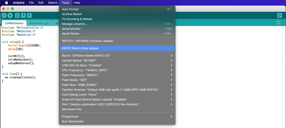
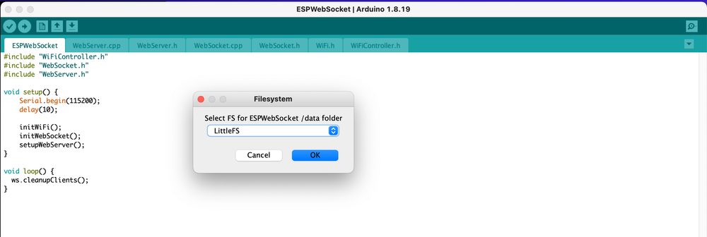
- Select "ESP32 Sketch Data Upload", choose "LittleFS" and click "OK"
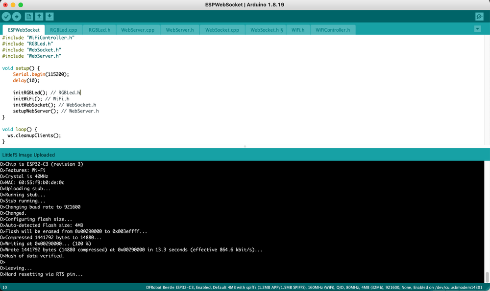
- The terminal will open and you should see the information about data upload. If it uploads successfully, the ESP32 will restart.
- Test the application
- If everything is installed successfully, in the Serial Monitor, you should see the logs as follows:
Connecting to WiFi ....192.168.129.8
Websocket started
LittleFS mounted successfully
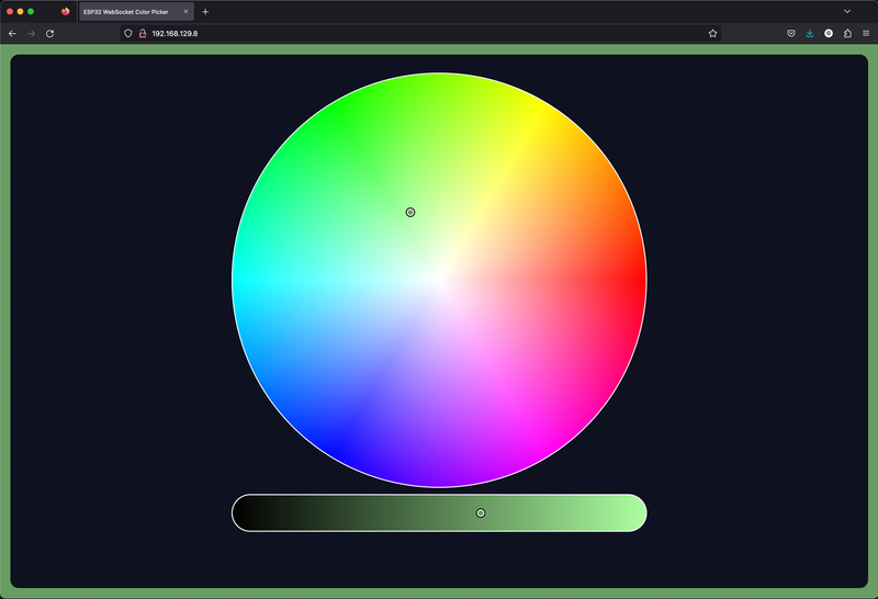
- Open your web browsers, such as Chrome or Firefox, and enter the IP address shown in the Serial Monitor. In our case
192.168.129.8. In the website opened you should see the color picker.
Control the RGB LED with the color picker #
On the opened website, try moving the marker on the color picker to adjust the color and the slider below to adjust the brightness.
If you want to make sure the Web Sockets are working correctly, open the same website on another device, such as your mobile phone. When moving the slider or marker on the color picker on one device, you should see it move synchronously on the other one also.
Conclusion and next steps #
In this post, we built a Website, that uses the iro.js color picker to control the RGB LED, connected to ESP32 with the Web Sockets.
We have built a simple responsive website, with the iro.js color picker, which provides an easy-to-use API and good design for the applications that need the color selectors.
After that, we built an application with the Web Server and Web Sockets server for the ESP32 microcontroller, which would receive the commands from the previously built Website and control the RGB LED, connected to the ESP32.
Next, we built a Web Socket client on the Website, which would be able to send the commands to the ESP32.
Finally, we connected everything and tested the application.
The application, that we build in this post, can be easily transformed to control the RGB LED Strip, instead of one RGB LED and with the help of iro.js pickers, can be extended to control the RGB CCT (Red + Green + Blue + Cold White + Warm White) led strips.
Also, the website is responsive and fits screens from desktop computers to mobile phone screens and therefore could be easily transformed into an Android or iOS application.
We will continue this project in the upcoming posts and will build an RGB CCT Led Strip controller.
In case you have noticed any errors, or need help, feel free to contact us, using the contacts form.