
ESP32 Strapping Pins: Complete List for All Chip Variants
ESP32 strapping pins explained for every chip variant: ESP32, S2, S3, C3, C6, H2. Complete GPIO boot mode table, safe pin selection guide, pins to avoid, and configuration tips.
Strapping pins are fundamental to all ESP32 microcontrollers, including the original ESP32, ESP32-S2, ESP32-S3, ESP32-C3, and ESP32-C6. Today we are going to explore the strapping pins common features and functions across different ESP32 versions.
| Chip | Strapping Pins | Download Mode Trigger |
|---|---|---|
| ESP32 | GPIO0 GPIO2 GPIO5 GPIO12 MTDI GPIO15 MTDO | GPIO0 LOW at boot |
ESP32-S2 S | GPIO0 GPIO45 GPIO46 | GPIO0 LOW at boot |
ESP32-S3 S | GPIO0 GPIO3 GPIO45 GPIO46 | GPIO0 LOW at boot |
ESP32-C3 C | GPIO2 GPIO8 GPIO9 | GPIO9 LOW + GPIO8 HIGH |
ESP32-C6 C | GPIO8 GPIO9 GPIO15 MTDI MTMS | GPIO9 LOW at boot |
ESP32-H2 H | GPIO8 GPIO9 | GPIO9 LOW at boot |
Want this offline? View full cheatsheet (PNG) →
Quick Answer
Strapping pins are special GPIO pins that configure ESP32 behavior at startup. Their primary function is boot mode selection — determining whether the chip enters download mode (for flashing firmware) or normal mode (to run your program).
Most modern dev boards handle this automatically via USB. Learn more →
Main Uses of Strapping Pins
The strapping pins on ESP32 microcontrollers control these four key functions:
Boot Mode
Flash or run mode
Voltage
SPI flash voltage
JTAG
Debug interface
ROM Messages
Boot output control
Understanding Strapping Pins
Strapping pins (also called bootstrap pins) are specialized GPIO pins that the ESP32 reads during boot to determine hardware configuration. During power-on or reset, the ROM bootloader samples these pins within microseconds to configure:
- Boot source - Flash memory, UART download, or USB download
- Flash voltage - 3.3V or 1.8V for SPI communication
- Debug routing - USB-JTAG or pad-based JTAG
- ROM messages - Enable or disable boot log output
The sampling happens only once during reset. After boot, these pins become regular GPIOs-but external components (resistors, LEDs, sensors) remain connected, so circuit design must ensure correct boot states.
Automatic Boot Mode on Modern Boards
Most ESP32 development boards manufactured since 2018 include automatic boot mode switching using DTR/RTS signals from the USB-to-serial chip, eliminating the need to manually press BOOT and RESET buttons.
How it works: When uploading firmware, the programming software (Arduino IDE, PlatformIO, esptool) automatically:
- Controls GPIO0 and RESET pins through transistors
- Pulls GPIO0 LOW while resetting to enter download mode
- Uploads firmware via UART
- Releases GPIO0 and resets again to run your program
Automatic Boot Mode
- ESP32-DevKitC V4 (Espressif official)
- NodeMCU-32S, WROOM-32 dev boards
- Boards with CP2102, CH340G, FT232 chips
- ESP32-S2/S3/C3 with native USB
Manual Buttons Required
- Bare ESP32 modules without dev board PCB
- Custom PCBs without auto-reset circuit
- Budget boards with simplified USB
- Basic USB-to-TTL adapters (no DTR/RTS)
Why strapping pins matter:
- Boot failures - Incorrect pin states are the #1 cause of "won't boot" errors. External components on wrong pins prevent startup. You can probe the pin voltage with a multimeter to confirm its state at boot.
- Firmware uploads - GPIO0 must be LOW to flash new code. Circuits holding it HIGH block uploads.
- Circuit design - Use series resistors (1kΩ-10kΩ) when connecting peripherals to strapping pins to avoid boot interference.
- Pin planning - Prioritize non-strapping pins for critical hardware. Save strapping pins for non-essential features.
Quick Reference: Strapping Pins by ESP32 Version
Here's a quick overview of all ESP32 versions at a glance:
ESP32
5 Strapping Pins
Boot, Voltage, JTAG, ROM
ESP32-S2
3 Strapping Pins
Boot, Voltage, JTAG, ROM
ESP32-S3
4 Strapping Pins
Boot, Voltage, JTAG, ROM
ESP32-C3
3 Strapping Pins
Boot, ROM Messages
ESP32-C6
5 Strapping Pins
Boot, SDIO, ROM, JTAG
ESP32-H2
2 Strapping Pins
Boot, ROM Messages
Which GPIO Pins Are Strapping Pins? Complete List by ESP32 Version
Here's the complete list of strapping pins for each ESP32 version with their boot mode configurations:
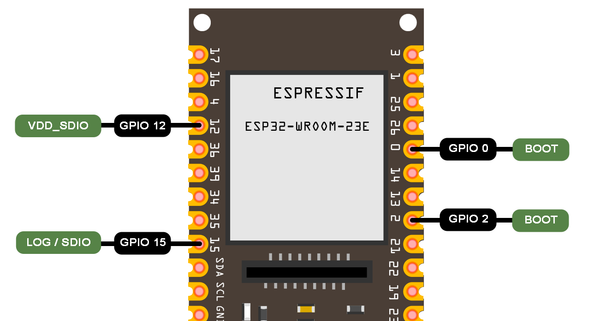
ESP32 (Original) Strapping Pins
Strapping Pins (5 Total)
Also known as: MTDI (GPIO12), MTDO (GPIO15)
Boot Mode Control
GPIO0 (Primary Boot Control)
Main pin that determines boot mode:
→ Download Mode (UART)
Programming/flashing mode via serial connection
→ SPI Flash Boot (Normal)
Default mode - boots from flash memory
+ GPIO2, GPIO12, GPIO15 affect boot mode selection and configuration
Other Functions
ESP32-S2 Strapping Pins
Strapping Pins (3 Total)
Boot Mode Control
GPIO0 (Primary Boot Control)
Main pin that determines boot mode:
→ Download Mode (UART)
Programming/flashing mode via serial connection
→ SPI Flash Boot (Normal)
Default mode - boots from flash memory
+ GPIO45, GPIO46 control additional configuration (voltage, debug messages, JTAG)
Other Functions
GPIO45
GPIO46
ESP32-S3 Strapping Pins
Strapping Pins (4 Total)
Boot Mode Control
GPIO0 (Primary Boot Control)
Main pin that determines boot mode:
→ Download Mode (UART)
Programming/flashing mode via serial connection
→ SPI Flash Boot (Normal)
Default mode - boots from flash memory
+ GPIO3, GPIO45, GPIO46 control additional configuration (JTAG, voltage, debug messages)
Other Functions
ESP32-C3 Strapping Pins
Strapping Pins (3 Total)
Boot Mode Control
GPIO2 + GPIO8 + GPIO9
Pin combinations determine boot mode:
→ SPI Flash Boot (Normal)
Default mode - boots from flash memory
→ Download Boot (UART)
Programming mode via serial connection
→ USB Download Boot
Programming via native USB interface
Other Functions
GPIO8
GPIO9
ESP32-C6 Strapping Pins
Strapping Pins (5 Total)
Boot Mode Control
GPIO8 + GPIO9
Pin combinations determine boot mode:
→ SPI Flash Boot (Normal)
Default mode - boots from flash memory
→ Download Boot (UART)
Programming mode via serial connection
Other Functions
ESP32-H2 Strapping Pins
Strapping Pins (2 Total)
Boot Mode Control
GPIO8 + GPIO9
Pin combinations determine boot mode:
→ SPI Flash Boot (Normal)
Default mode - boots from flash memory
→ Download Boot (UART)
Programming mode via serial connection
Other Functions
GPIO8
Key Observations
Common Across All Versions:
- GPIO0 is used for boot mode (except C3, C6, H2)
- GPIO8/GPIO9 control ROM messages
- All support boot mode selection
Version-Specific:
- S2/S3: GPIO45/46 for VDD_SPI voltage
- C6: Has SDIO edge control
- C3/H2: Simplified (fewer pins)
Common Strapping Features Across ESP32 Versions
Strapping pins control four main hardware configurations across ESP32 variants. Here's a detailed look at each function:
Boot Mode Selection
Determines whether the ESP32 boots into normal operation mode (to run your program) or download mode (to receive new firmware via USB/UART).
Why it's important: This is the most critical strapping pin function. Without proper boot mode control, you cannot upload firmware to your ESP32. Every time you flash new code, the chip must enter download mode first, then reset to normal mode to run the code.
ESP32, ESP32-S2, ESP32-S3
- GPIO0 = LOW (0V): Download Mode - ready to receive firmware
- GPIO0 = HIGH (3.3V): Normal Mode - executes program from flash
- Most dev boards have a "BOOT" button connected to GPIO0
ESP32-C3, ESP32-C6, ESP32-H2
- Uses combinations of GPIO2, GPIO8, GPIO9
- Different pin combinations select different boot sources
- Refer to version-specific cards above for exact combinations
Voltage Selection (VDD_SPI / VDD_SDIO)
Configures the operating voltage (1.8V or 3.3V) for the SPI flash memory chip that stores your program code and data. Some ESP32 modules support both voltage levels.
Why it's important: Using the wrong voltage can damage your flash memory chip or cause communication failures. Most ESP32 modules use 3.3V flash (most common), but some specialized boards use 1.8V flash for lower power consumption. The voltage must match your hardware.
VDD_SPI Configuration:
ESP32-S2, ESP32-S3, ESP32-C3
GPIO45 controls VDD_SPI voltage selection at boot:
- GPIO45 with external pull-down: Sets to 1.8V mode
- GPIO45 with external pull-up: Sets to 3.3V mode (default)
- Can also be controlled by eFuse bits for permanent configuration
ESP32-C6 (VDD_SDIO)
Similar function but for SDIO interface voltage when using SD cards or other SDIO peripherals. Controls voltage supplied to external SDIO devices.
Warning: Most users don't need to modify this setting. Pre-built ESP32 modules already have the correct pull-up/pull-down resistors for their flash chip. Only change this if you're designing custom hardware.
JTAG Signal Source Control
Determines whether JTAG debugging signals come from USB (built-in USB-JTAG controller) or external debug pins (traditional JTAG pads). JTAG allows real-time debugging, breakpoints, and memory inspection.
Why it's important: Proper JTAG configuration is essential for advanced debugging with tools like OpenOCD or ESP-IDF's debugging features. It determines whether you debug via USB cable or external JTAG hardware (like J-Link or FT2232H).
GPIO15 Configuration (ESP32-S2/S3):
GPIO15 = LOW: USB JTAG
Debug via USB cable — no external hardware needed. Best for most developers using Arduino IDE or PlatformIO.
GPIO15 = HIGH: External JTAG
Use with J-Link, FT2232H, or other external JTAG adapters for advanced debugging scenarios.
Note: Works in conjunction with eFuse settings (EFUSE_DIS_PAD_JTAG, EFUSE_DIS_USB_JTAG) which can permanently disable certain JTAG sources for security.
JTAG Pin Name Aliases (MTDI, MTDO, MTCK, MTMS)
ESP32 datasheets and pinout diagrams use legacy JTAG signal names alongside GPIO numbers. These aliases appear frequently in IDE warnings and community discussions:
| Alias | GPIO (ESP32) | JTAG Signal | Also used as strapping pin? |
|---|---|---|---|
| MTDI | GPIO12 | TDI (Test Data In) | Yes - VDD_SDIO voltage (ESP32); VDD_SPI voltage (ESP32-C6) |
| MTDO | GPIO15 | TDO (Test Data Out) | Yes - ROM message enable (ESP32) |
| MTCK | GPIO13 | TCK (Test Clock) | No - regular GPIO on most variants |
| MTMS | GPIO14 | TMS (Test Mode Select) | Yes - VDD_SPI voltage (ESP32-C6 only) |
ROM Boot Messages
Controls whether the ESP32's ROM bootloader prints diagnostic messages during the boot process. These messages show boot mode, flash configuration, and any boot errors.
Why it's important: ROM messages are extremely useful for debugging boot failures, but you may want to disable them in production devices to reduce power consumption, boot time, or prevent information leakage.
How GPIO8/GPIO9 Control Messages:
When Enabled:
- See detailed boot sequence messages
- Flash size, speed, and mode information
- Error messages if boot fails
- Helps diagnose hardware or flash configuration problems
When Disabled:
- Cleaner serial output (only your application's messages)
- Slightly faster boot time
- Prevents exposing internal boot information
- Preferred for production/commercial devices
Output destinations: Messages can be routed to UART0 (default serial port) or USB Serial/JTAG Controller depending on configuration and eFuse settings.
Using Strapping Pins as Regular GPIO
While strapping pins primarily serve as configuration parameters during the boot process, this doesn't mean the pins must be left alone after the initial configuration.
Once the ESP32 microcontroller has successfully initialized, these pins transform into regular GPIO (General Purpose Input/Output) pins, available for user-defined functions. However, you must be careful when manipulating these pins during and immediately after the boot phase.
Can you use strapping pins as regular GPIOs? Yes, but with important caveats:
Safe After Boot
- Read input from sensors
- Control LEDs or outputs
- Use for communication protocols (I2C, SPI)
- Any normal GPIO function
Watch Out For
- External pull-ups/downs affecting boot state
- Components that hold pins LOW/HIGH at boot
- Reset scenarios that re-check strapping pins
- Brownout conditions triggering re-boot
Design considerations:
- Use series resistors (1kΩ-10kΩ) when connecting peripherals to strapping pins. This allows the internal pull-ups/downs to dominate during boot.
- Avoid strong pull-ups/downs that could override the ESP32's boot configuration.
- Test your design through multiple power cycles and resets to ensure consistent booting.
- Prioritize non-strapping pins for critical functions when possible.
Best practice: In an ideal scenario, avoid using strapping pins for critical hardware connections. If you must use them, ensure your external circuitry doesn't interfere with the required boot states. When in doubt, use non-strapping GPIO pins.
Can I Use GPIO0, GPIO2, or GPIO12 as Output After Boot?
Yes - all strapping pins become fully general-purpose GPIOs once the ROM bootloader finishes sampling them (within ~100 ms of reset). Here's the practical guidance for each commonly questioned pin:
GPIO0 - safe for input/output after boot
Avoid driving it LOW at power-on or during reset. If used for a button or LED, a series resistor (1 kΩ–10 kΩ) protects the boot state. Most dev boards already pull it HIGH via an internal resistor.
GPIO2 - safe for output after boot (ESP32 original)
Must be HIGH or floating at boot for normal SPI Flash mode. Connecting a LED with a pull-down is the most common cause of boot problems with GPIO2 - use a 10 kΩ series resistor.
GPIO12 (MTDI) - use with caution
This is the most dangerous strapping pin. If GPIO12 is pulled HIGH at boot, the ESP32 switches to 1.8 V flash mode, which will crash or damage modules with 3.3 V flash. Keep this pin floating or pull it LOW (or burn the VDD_SDIO eFuse to 3.3 V permanently). Safe to drive as output only after boot completes.
Arduino IDE and ESPHome Strapping Pin Warnings
You may see warnings like these when using strapping pins in your sketches or YAML config:
W (xxx) gpio: GPIO 5 is a strapping pin and should only be used for non-critical I/O.
W (xxx) gpio: GPIO 0 is a strapping pin and should only be used for non-critical I/O.
W (xxx) gpio: GPIO 2 is a strapping pin and should only be used for non-critical I/O.
These warnings come from the ESP-IDF GPIO driver and are informational - they do not mean the pin doesn't work. The warning fires whenever you configure a strapping pin as GPIO. What it means:
What triggers it
gpio_config()orpinMode()called on GPIO0, 2, 5, 12, or 15- ESPHome
output:orbinary_sensor:on same pins - Any framework that calls the GPIO driver internally
How to handle it
- For GPIO5: safe to use after boot - suppress the warning if it's distracting
- For GPIO12: verify your module uses 3.3 V flash before driving it HIGH
- For GPIO0: ensure nothing holds it LOW during power-on
ESP32 GPIO Pins to Avoid: Safe Pin Selection Guide
To revise once more, let's take a look at the strapping pins on different ESP32 versions. Strapping pins are used to set configurations such as ESP32 programming mode or specific boot behaviors.
It's important to identify ESP32 reserved pins and avoid using them as GPIO pins, as they are required during boot-up and certain operational modes. The table below provides an overview of ESP32 programming pins, ESP32 pins to avoid, and their default configurations.
| ESP32 Version | Strapping Pins to Avoid |
|---|---|
| ESP32 | GPIO0, GPIO2, GPIO5, GPIO12 (MTDI), GPIO15 (MTDO) |
| ESP32-S2 | GPIO0, GPIO45, GPIO46 |
| ESP32-S3 | GPIO0, GPIO3, GPIO45, GPIO46 |
| ESP32-C3 | GPIO2, GPIO8, GPIO9 |
| ESP32-C6 | GPIO8, GPIO9, MTDI (GPIO12), GPIO14 (MTMS), GPIO15 |
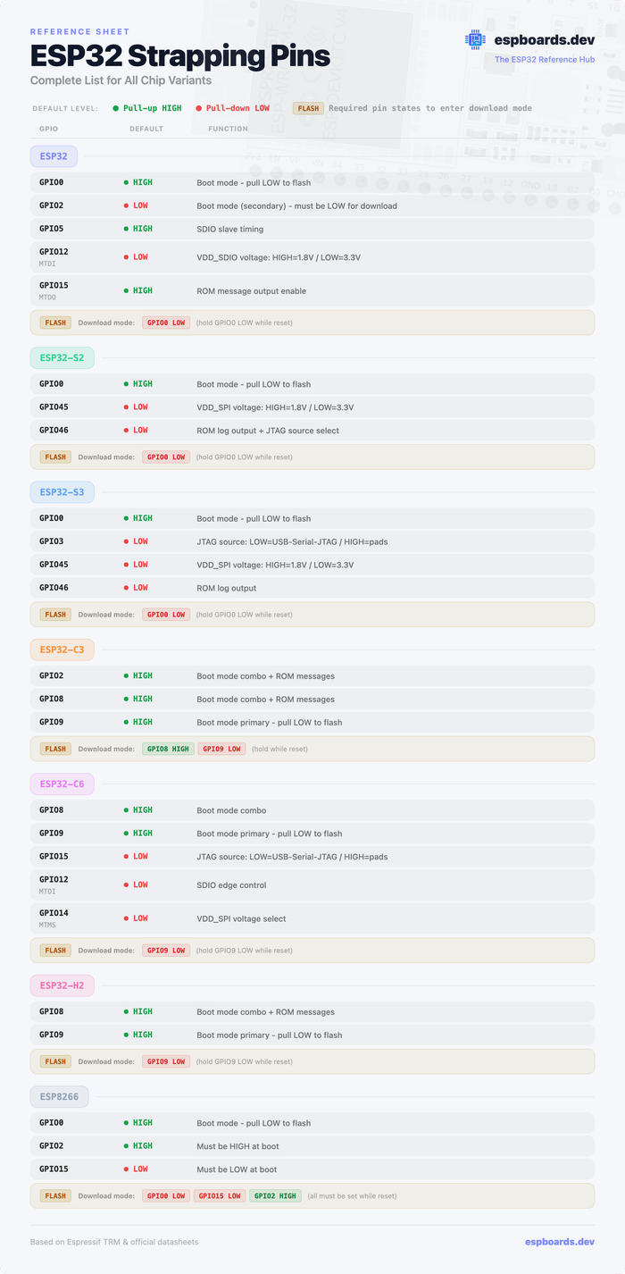
ESP32 Strapping Pins Cheatsheet
All chip variants - boot modes, GPIO levels, download mode
ESP32 Strapping Pins Cheatsheet
All chip variants - boot modes, GPIO levels, download mode
ESP8266 Strapping Pins
While this guide focuses on the ESP32 family, the ESP8266 uses a similar strapping pin concept at boot. If you're working with an ESP8266 (e.g., NodeMCU, Wemos D1 Mini), here are its three boot-critical pins:
| Pin | Required State at Boot | Effect |
|---|---|---|
| GPIO0 | HIGH = normal boot LOW = download mode | Primary boot mode control - same role as on ESP32 |
| GPIO2 | HIGH required (internal pull-up) | Must be HIGH at boot - LOW causes boot failure. Also TXD1 (second UART TX). |
| GPIO15 | LOW required (external pull-down on most modules) | Must be LOW at boot - HIGH causes boot failure. Also SPI CS / HSPI CS0. |
ESP8266 vs ESP32: The ESP8266 is less forgiving than the ESP32 - GPIO2 and GPIO15 have no flexibility (they must be HIGH and LOW respectively, always). Most ESP8266 dev boards include the correct pull-up/pull-down resistors on-board, so you only need to worry about this when designing custom PCBs.
Additional Resources
ESP32 Series Datasheet
Official ESP32 documentation
ESP32-S2 Series Datasheet
Official ESP32-S2 documentation
ESP32-S3 Series Datasheet
Official ESP32-S3 documentation
ESP32-C3 Series Datasheet
Official ESP32-C3 documentation
ESP32-C6 Series Datasheet
Official ESP32-C6 documentation
Conclusion
In conclusion, strapping pins play an important role in the initialization and configuration of various ESP32 microcontroller versions, including ESP32-S2, ESP32-S3, ESP32-C3, and ESP32-C6. These pins serve as gatekeepers, influencing critical parameters during startup or reset, such as boot mode, voltage selection, JTAG signal source, and more.
Across different ESP32 versions, certain common strapping pins persist, each with its unique functions and default configurations. GPIO0, for instance, is the most commonly used strapping pin, which is used to select the boot mode.