
ESP32 HW-394 (WR-32) is a development board based on the ESP32 microcontroller using XTENSA architecture.
This board features a maximum CPU frequency of 240 MHz and 4MB flash memory.
About ESP32 HW-394 (WR-32)
The ESP32 HW-394 (WR-32) is a compact development board based on the ESP32 WROOM-32 module, featuring integrated Wi-Fi 802.11 b/g/n and Bluetooth 4.2 + BLE for seamless wireless connectivity. 📶
With a dual-core Xtensa 32-bit LX6 processor running up to 240 MHz, 4MB flash memory, and 520KB SRAM, it's perfect for IoT projects, home automation, and embedded applications. ⚡
The board offers 34 GPIO pins with support for ADC (18 channels, 12-bit), DAC (2 channels), PWM, and various communication interfaces including UART, SPI, I2C, I2S, CAN, and Ethernet MAC. 🔌
Operating at 3.3V with ultra-low power consumption in deep sleep mode (as low as 10 µA), it's ideal for battery-powered devices. 🔋 Compact dimensions of 18mm x 25.5mm make it suitable for space-constrained designs. 📏
Where to Buy ESP32 HW-394 (WR-32)

Starting from
$5 per unit

Prices are subject to change. We earn from qualifying purchases as an Amazon Associate.
Technical Specifications
Complete technical specification details for ESP32 HW-394 (WR-32)
USB
Connectivity
Microcontroller
✨ Features & Pins
Quick Setup
Copy-paste configs for ESP32 HW-394 (WR-32) - auto‑generated from this board's exact hardware specs.
In Arduino IDE 2 select Esp32 Hw 394 from the esp32 by Espressif package. In PlatformIO use board = esp32dev. ESP32 · 240 MHz · 4MB · DIO.
In Arduino IDE 2, open Boards Manager, search "esp32" by Espressif and install it. Then go to Tools → Board and select "Esp32 Hw 394" for the ESP32 HW-394 (WR-32).
ESP32 HW-394 (WR-32) Pinout Diagram
Complete pin reference for ESP32 HW-394 (WR-32)
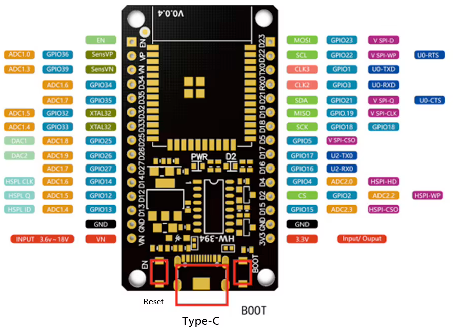
The ESP32 HW-394 pinout is based on the ESP32 WROOM-32 module with 38 pins, providing extensive functionality in a compact form. Key power pins include 3V3 for 3.3V input and GND for ground connection, ensuring stable power for the module.
The pinout features dedicated communication pins such as TXD0 and RXD0 for UART0, and GPIO pins like IO0 to IO16 for general-purpose I/O. ADC channels (ADC1_CH0 and others) support 12-bit analog input for sensor readings, while DAC1 provides analog output capabilities.
Additional pins include EN for module enable and various GPIOs configurable for SPI, I2C, PWM, and more. This versatile pinout supports digital I/O, analog functions, and multiple protocols, making the ESP32 HW-394 suitable for diverse IoT and embedded projects.
Safe Pins to Use
These pins are safe for general GPIO usage without boot or system conflicts
Why Are These Pins Safe?
Pins to Avoid or Use with Caution
Reserved for critical functions. Misuse may cause boot failures, programming issues, or system conflicts.
Boot behavior & flash voltage
Low-level debugging interface
USB Serial/JTAG communication
Memory & PSRAM connections
Debugging & firmware uploads
| PIN | Label | Why Avoid | Type |
|---|---|---|---|
| IO0 | GPIO0 | Must be HIGH during boot for normal startup; if held LOW on reset, forces flash programming mode. | 🛠️ Strapping |
| IO2 | GPIO2 | If driven HIGH on reset (while IO0 is LOW), selects an unsupported SDIO boot mode, causing boot failure. | 🛠️ Strapping |
| IO4 | GPIO4 | Sampled at reset for boot config; should not be driven at boot (affects boot mode timing). | 🛠️ Strapping |
| IO5 | GPIO5 | Must be HIGH during boot; if pulled LOW at reset, alters SDIO slave timing and may prevent normal boot. | 🛠️ Strapping |
| IO12 | MTDI (GPIO12) | Keep LOW during boot (internal PD); pulling HIGH at reset selects 1.8V flash mode, causing flash brownout if 3.3V flash is used. | 🛠️ Strapping |
| IO13 | MTCK (GPIO13) | Used for JTAG debugging (TCK); avoid using as GPIO if JTAG is needed. | 🪛 Other |
| IO14 | MTMS (GPIO14) | Used for JTAG debugging (TMS); driving it as GPIO may interfere with JTAG or produce spurious signals at boot. | 🪛 Other |
| IO15 | MTDO (GPIO15) | Keep HIGH during boot (internal PU); if LOW on reset, bootloader log is silenced and boot mode may change. | 🛠️ Strapping |
| IO16 | GPIO16 | Connected to internal PSRAM on PSRAM-enabled modules; not usable as GPIO on those modules. | ⚡ Flash |
| IO17 | GPIO17 | Connected to internal PSRAM on PSRAM-enabled modules; not usable as GPIO on those modules. | ⚡ Flash |
| IO34 | GPIO34 | Cannot be used as output (no drive capability); only suitable for analog/digital input. | 🪛 Other |
| IO35 | GPIO35 | Cannot be used as output; only suitable for input. | 🪛 Other |
ESP32 HW-394 (WR-32) Additional Information
More details about ESP32 HW-394 (WR-32)

ESP32 HW-394 Variants
🔌 Different Models
- Flash Memory: Typically 4MB, but check specifications as some variants might differ.
- Board Layout: Slight differences in component placement or additional features like onboard LEDs.
⚙️ Compatibility Notes
All variants are based on the ESP32 WROOM-32 module and should be compatible with standard ESP32 development tools. Always verify the pinout and specifications for your specific board version.
💡 Choosing the Right Variant
Look for boards with reliable USB chips and sufficient flash memory for your project needs. The HW-394 is a cost-effective option for ESP32 prototyping.
Useful Links
Datasheets and resources for ESP32 HW-394 (WR-32)
ESP32 HW-394 (WR-32) Custom Pin Mapping
Pin configuration and GPIO mapping for ESP32 HW-394 (WR-32)
| Pin | Function | ESP Pin | I/O Type | Description |
|---|---|---|---|---|
| 6 | IO0 | GPIO0 | BIDIRECTIONAL | GPIO0, Boot Mode Selection |
| 7 | IO2 | GPIO2 | BIDIRECTIONAL | GPIO2, General Purpose I/O |
| 8 | IO4 | GPIO4 | BIDIRECTIONAL | GPIO4, General Purpose I/O |
| 9 | IO5 | GPIO5 | BIDIRECTIONAL | GPIO5, General Purpose I/O |
| 10 | IO12 | GPIO12 | BIDIRECTIONAL | GPIO12, ADC or GPIO |
| 11 | IO13 | GPIO13 | BIDIRECTIONAL | GPIO13, ADC or GPIO |
| 12 | IO14 | GPIO14 | BIDIRECTIONAL | GPIO14, ADC or GPIO |
| 13 | IO15 | GPIO15 | BIDIRECTIONAL | GPIO15, ADC or GPIO |
| 14 | IO16 | GPIO16 | BIDIRECTIONAL | GPIO16, General Purpose I/O |
| 15 | RX | GPIO3 | INPUT | UART0 Receive |
| 16 | TX | GPIO1 | OUTPUT | UART0 Transmit |
| 17 | IO17 | GPIO17 | BIDIRECTIONAL | GPIO17, General Purpose I/O |
| 18 | IO18 | GPIO18 | BIDIRECTIONAL | GPIO18, General Purpose I/O |
| 19 | IO19 | GPIO19 | BIDIRECTIONAL | GPIO19, General Purpose I/O |
| 20 | IO21 | GPIO21 | BIDIRECTIONAL | GPIO21, I2C SDA |
| 21 | IO22 | GPIO22 | BIDIRECTIONAL | GPIO22, I2C SCL |
| 22 | IO23 | GPIO23 | BIDIRECTIONAL | GPIO23, SPI MOSI |
| 23 | IO25 | GPIO25 | BIDIRECTIONAL | GPIO25, DAC1 |
| 24 | IO26 | GPIO26 | BIDIRECTIONAL | GPIO26, DAC2 |
| 25 | IO27 | GPIO27 | BIDIRECTIONAL | GPIO27, ADC |
| 26 | IO32 | GPIO32 | BIDIRECTIONAL | GPIO32, ADC |
| 27 | IO33 | GPIO33 | BIDIRECTIONAL | GPIO33, ADC |
| 28 | IO34 | GPIO34 | INPUT | GPIO34, ADC Input Only |
| 29 | IO35 | GPIO35 | INPUT | GPIO35, ADC Input Only |
Pin Mappings
Complete pinout and GPIO mapping for ESP32 HW-394 (WR-32)
| Pin | Analog | Touch | PWM | Other |
|---|---|---|---|---|
| 0 | T1 | |||
| 1 | PWM | TX | ||
| 2 | A12 | T2 | PWM | |
| 3 | PWM | RX | ||
| 4 | A10 | T0 | PWM | |
| 5 | PWM | |||
| 12 | A15 | T5 | PWM | |
| 13 | A14 | T4 | PWM | |
| 14 | A16 | T6 | PWM | |
| 15 | A13 | T3 | PWM | |
| 16 | PWM | |||
| 17 | PWM | |||
| 18 | PWM | |||
| 19 | PWM | |||
| 21 | PWM | SDA | ||
| 22 | PWM | SCL | ||
| 23 | PWM | MOSI | ||
| 25 | A18 | DAC1 | ||
| 26 | A19 | DAC2 | ||
| 27 | A17 | T8 | PWM | |
| 32 | A4 | T9 | PWM | |
| 33 | A5 | T10 | PWM | |
| 34 | A6 | INPUT | ||
| 35 | A7 | INPUT |
Default Tools & Configuration
Build and upload settings for ESP32 HW-394 (WR-32)
| Setting | Value |
|---|---|
| Bootloader tool | esptool_py |
| Uploader tool | esptool_py |
| Network uploader tool | esp_ota |
| Bootloader address | 0x1000 |
| Flash mode | dio |
| Boot mode | dio |
| Maximum upload size | 1280 KB (1310720 bytes) |
| Maximum data size | 320 KB (327680 bytes) |
The ESP32 HW-394 (WR-32) uses esptool_py for uploads , esp_ota for OTA updates, and esptool_py bootloader at 0x1000.
Flash mode: dio | Boot mode: dio
Max sketch size: 1280 KB | Max data size: 320 KB
Similar Boards
Other development boards with ESP32 microcontroller

Frog Board ESP32
Frog Board ESP32 development board is based on esp32 microcontroller and uses xtensa architecture.

Dongsen Tech Pocket 32
Dongsen Tech Pocket 32 development board is based on esp32 microcontroller and uses xtensa architecture.

ESP32 Wrover Module
ESP32 Wrover Module development board is based on esp32 microcontroller and uses xtensa architecture.