
AI Thinker ESP32-CAM is a development board based on the ESP32 microcontroller using XTENSA architecture.
This board features a maximum CPU frequency of 240 MHz and 4MB flash memory.
About AI Thinker ESP32-CAM
Where to Buy AI Thinker ESP32-CAM

Starting from
10$ per unit


Prices are subject to change. We earn from qualifying purchases as an Amazon Associate.
Technical Specifications
Complete technical specification details for AI Thinker ESP32-CAM
Connectivity
Microcontroller
✨ Features & Pins
Quick Setup
Copy-paste configs for AI Thinker ESP32-CAM - auto‑generated from this board's exact hardware specs.
In Arduino IDE 2 select Esp32 Dev from the esp32 by Espressif package. In PlatformIO use board = esp32dev. ESP32 · 240 MHz · 4MB · DIO.
In Arduino IDE 2, open Boards Manager, search "esp32" by Espressif and install it. Then go to Tools → Board and select "Esp32 Dev" for the AI Thinker ESP32-CAM.
AI Thinker ESP32-CAM Pinout Diagram
Complete pin reference for AI Thinker ESP32-CAM
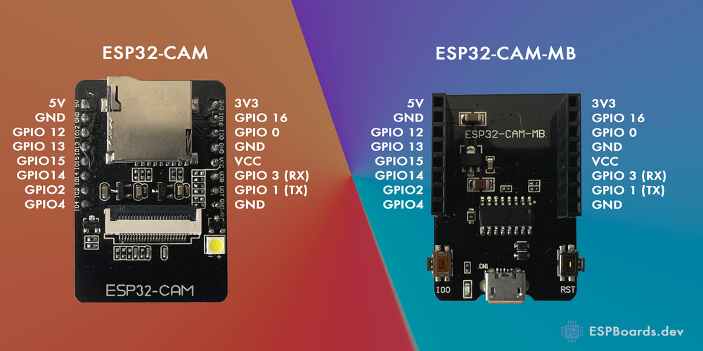
The ESP32-CAM pinout is designed to provide versatile functionality for camera-based IoT applications. It features essential power pins like 5V, 3.3V, and GND, ensuring stable power delivery for both the ESP32 chip and connected peripherals.
For communication, the ESP32-CAM (also written as ESP32CAM, ESP 32 CAM, or ESP-CAM) includes RX and TX for UART, making it easy to connect to external serial devices. Additionally, SDA and SCL support I2C communication, while SPI pins like MISO, MOSI, SCK, and SS enable high-speed data transfer for sensors, displays, and storage.
One of the key features of the ESP32-CAM is its dedicated camera interface, which includes multiple GPIOs for connecting the OV2640 camera module. It also has a microSD card slot, allowing you to store captured images and videos easily.
Since the ESP32-CAM does not have a built-in USB-to-serial converter, programming requires an external FTDI or USB-to-TTL adapter connected to the RX and TX pins. Proper boot mode selection is also necessary when flashing firmware.
⚠️ Pins to Avoid or Use with Caution
| Pin Name | Label | Reason to Avoid |
|---|---|---|
| IO0 | BOOT | Must be pulled low to enter flash mode. Avoid using as a regular GPIO. |
| IO4 | CAM_D2 | Used by the camera module. Avoid using if the camera is in use. |
| IO12 | MTDI | Bootstrapping pin. Can cause issues if pulled high at startup. |
| IO13 | MTCK | Used for flash mode configuration. Avoid using if unsure. |
| IO14 | MTMS | Connected to the camera. Avoid using as a general GPIO. |
| IO15 | MTDO | Strapping pin. Can interfere with boot mode if pulled incorrectly. |
For general GPIO usage, IO2, IO16, and IO17 are the safest and most flexible choices. 🚀
Useful Links
Datasheets and resources for AI Thinker ESP32-CAM
Frequently Asked Questions
Common questions about AI Thinker ESP32-CAM
What is the ESP32-CAM used for?
The ESP32-CAM is a low-cost Wi-Fi and Bluetooth-enabled camera module designed for IoT, security, and AI vision applications. It includes an OV2640 camera, a microSD card slot, and GPIO pins for connecting sensors and peripherals.
What voltage does the ESP32-CAM require?
The ESP32-CAM operates on a 5V supply through its 5V pin. The onboard voltage regulator provides 3.3V to the ESP32 chip and connected components.
What is the resolution of the ESP32-CAM's OV2640 camera?
The default OV2640 camera module supports resolutions up to 1600×1200 pixels (UXGA), with common modes including 640×480 (VGA) and 800×600 (SVGA) for streaming.
Does the ESP32-CAM have Bluetooth?
Yes, the ESP32-CAM supports Bluetooth 4.2 BR/EDR and Bluetooth Low Energy (BLE) via the integrated ESP32-S SoC.
How do I program the ESP32-CAM?
Since it lacks a built-in USB-to-serial converter, the ESP32-CAM must be programmed using an external FTDI or USB-to-TTL adapter connected to its RX and TX pins. IO0 should be pulled low to enter flashing mode.
Pin Mappings
Complete pinout and GPIO mapping for AI Thinker ESP32-CAM
| Pin | Analog | Touch | PWM | Other |
|---|---|---|---|---|
| 0 | A11 | T1 | ||
| 1 | PWM | TX | ||
| 2 | A12 | T2 | PWM | |
| 3 | PWM | RX | ||
| 4 | A10 | T0 | PWM | |
| 5 | PWM | SS | ||
| 12 | A15 | T5 | PWM | |
| 13 | A14 | T4 | PWM | |
| 14 | A16 | T6 | PWM | |
| 15 | A13 | T3 | PWM | |
| 18 | PWM | SCK | ||
| 19 | PWM | MISO | ||
| 21 | PWM | SDA | ||
| 22 | PWM | SCL | ||
| 23 | PWM | MOSI | ||
| 25 | A18 | PWM | DAC1 | |
| 26 | A19 | PWM | DAC2 | |
| 27 | A17 | T7 | PWM | |
| 32 | A4 | T9 | PWM | |
| 33 | A5 | T8 | PWM | |
| 34 | A6 | |||
| 35 | A7 | |||
| 36 | A0 | |||
| 39 | A3 |
Default Tools & Configuration
Build and upload settings for AI Thinker ESP32-CAM
| Setting | Value |
|---|---|
| Bootloader tool | esptool_py |
| Uploader tool | esptool_py |
| Network uploader tool | esp_ota |
| Bootloader address | 0x1000 |
| Maximum upload size | 3072 KB (3145728 bytes) |
| Maximum data size | 320 KB (327680 bytes) |
The AI Thinker ESP32-CAM uses esptool_py for uploads , esp_ota for OTA updates, and esptool_py bootloader at 0x1000.
Flash mode: | Boot mode:
Max sketch size: 3072 KB | Max data size: 320 KB
Similar Boards
Other development boards with ESP32 microcontroller

IntoRobot Fig
IntoRobot Fig development board is based on esp32 microcontroller and uses xtensa architecture.

Espressif ESP32-LyraTD-DSPG
Espressif ESP32-LyraTD-DSPG development board is based on esp32 microcontroller and uses xtensa architecture.

ESP32 Dev Module
ESP32 Dev Module development board is based on esp32 microcontroller and uses xtensa architecture.