
M5Stack-Core2 is a development board based on the ESP32 microcontroller using XTENSA architecture.
This board features a maximum CPU frequency of 240 MHz and 16MB flash memory.
About M5Stack-Core2
Advanced ESP32 touchscreen dev kit with IMU, mic, and speaker - great for interactive and multimedia IoT.
Technical Specifications
Complete technical specification details for M5Stack-Core2
Display
Connectivity
Microcontroller
✨ Features & Pins
Quick Setup
Copy-paste configs for M5Stack-Core2 - auto‑generated from this board's exact hardware specs.
In Arduino IDE 2 select M5stack Core2 from the esp32 by Espressif package. In PlatformIO use board = esp32dev. ESP32 · 240 MHz · 16MB · DIO.
In Arduino IDE 2, open Boards Manager, search "esp32" by Espressif and install it. Then go to Tools → Board and select "M5stack Core2" for the M5Stack-Core2.
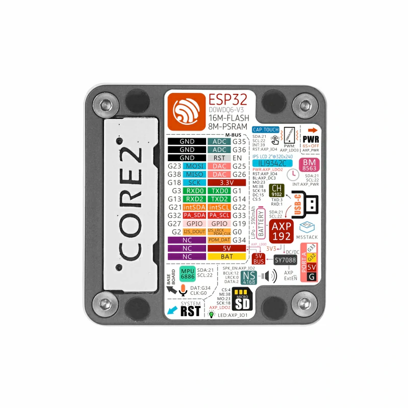
M5Stack-Core2 Pinout Diagram
Complete pin reference for M5Stack-Core2
Useful Links
Datasheets and resources for M5Stack-Core2
Pin Mappings
Complete pinout and GPIO mapping for M5Stack-Core2
| Pin | Analog | Touch | PWM | Other |
|---|---|---|---|---|
| 0 | G0 | |||
| 1 | PWM | TX G1 | ||
| 2 | PWM | G2 | ||
| 3 | PWM | RX G3 | ||
| 5 | PWM | SS G5 | ||
| 12 | PWM | G12 | ||
| 13 | PWM | RX2 G13 | ||
| 14 | PWM | TX2 G14 | ||
| 15 | PWM | G15 | ||
| 17 | PWM | G17 | ||
| 18 | PWM | SCK G18 | ||
| 19 | PWM | G19 | ||
| 21 | PWM | G21 | ||
| 22 | PWM | G22 | ||
| 23 | PWM | MOSI G23 | ||
| 25 | PWM | G25 DAC1 | ||
| 26 | PWM | G26 DAC2 | ||
| 27 | PWM | G27 | ||
| 32 | PWM | SDA G32 | ||
| 33 | PWM | SCL G33 | ||
| 34 | G34 | |||
| 35 | G35 ADC1 | |||
| 36 | G36 ADC2 | |||
| 38 | MISO G38 |
Default Tools & Configuration
Build and upload settings for M5Stack-Core2
| Setting | Value |
|---|---|
| Bootloader tool | esptool_py |
| Uploader tool | esptool_py |
| Network uploader tool | esp_ota |
| Bootloader address | 0x1000 |
| Flash mode | dio |
| Boot mode | dio |
| Maximum upload size | 6400 KB (6553600 bytes) |
| Maximum data size | 4416 KB (4521984 bytes) |
The M5Stack-Core2 uses esptool_py for uploads , esp_ota for OTA updates, and esptool_py bootloader at 0x1000.
Flash mode: dio | Boot mode: dio
Max sketch size: 6400 KB | Max data size: 4416 KB
Similar Boards
Other development boards with ESP32 microcontroller

M5Stack-FIRE
M5Stack-FIRE development board is based on esp32 microcontroller and uses xtensa architecture.

M5Stack-Station
M5Stack-Station development board is based on esp32 microcontroller and uses xtensa architecture.

M5Stack-ATOM
M5Stack-ATOM development board is based on esp32 microcontroller and uses xtensa architecture.