
TTGO T-Call (LilyGO)
ESP32 development board with GSM/GPRS cellular connectivity, supporting SIM800H and A7670E modules for IoT and remote communication projects.

TTGO T-Call (LilyGO) Pinout
24 pins · 2.54 mm pitch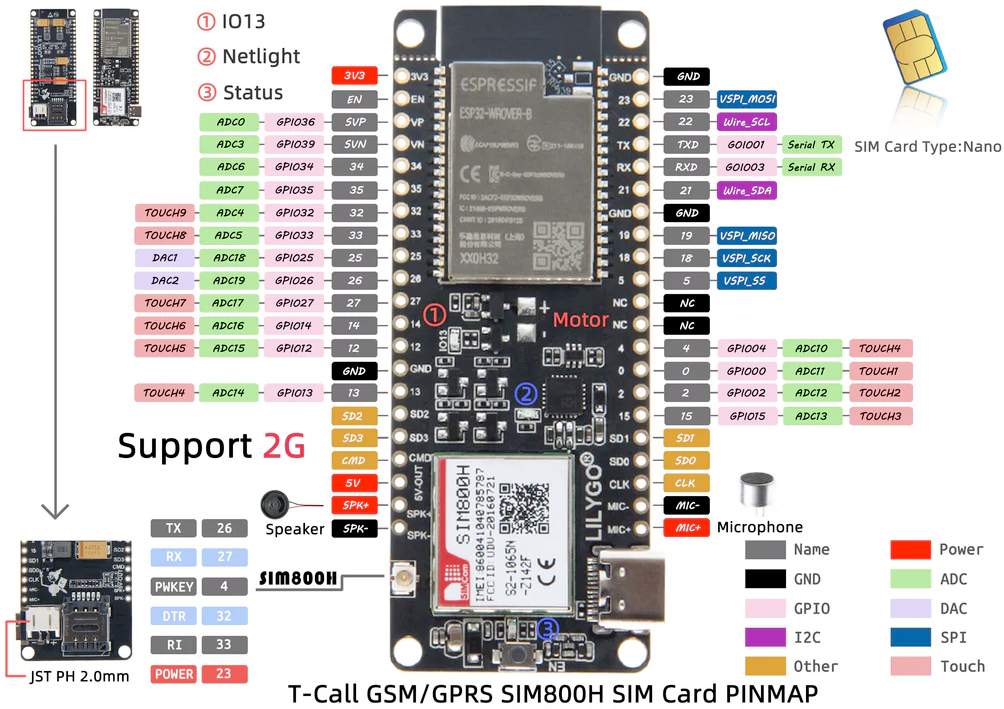
| Pin | GPIO | Labels | Status | Capabilities | Notes |
|---|---|---|---|---|---|
| 1 | 0 | IO0GPIO0 | strapping | - | GPIO0, Boot Mode Selection |
| 2 | 2 | IO2GPIO2 | strapping | - | GPIO2, General Purpose I/O |
| 3 | 4 | IO4GPIO4 | control | - | SIM800L modem PWRKEY (MODEM_PWRKEY); GPIO4 / ADC10 / TOUCH4 on header |
| 4 | 5 | IO5GPIO5 | control | - | SIM800L modem reset (MODEM_RST); GPIO5 / VSPI_SS on header |
| 5 | 12 | IO12GPIO12 | strapping | adc | GPIO12, ADC or GPIO |
| 6 | 13 | IO13GPIO13 | strapping | adc | GPIO13, ADC or GPIO |
| 7 | 14 | IO14GPIO14 | strapping | adc | GPIO14, ADC or GPIO |
| 8 | 15 | IO15GPIO15 | strapping | adc | GPIO15, ADC or GPIO |
| 9 | 16 | IO16GPIO16 | strapping | - | GPIO16, General Purpose I/O |
| 10 | 3 | RXD0GPIO3 | uart | uart | UART0 Receive |
| 11 | 1 | TXD0GPIO1 | uart | uart | UART0 Transmit |
| 12 | 17 | IO17GPIO17 | strapping | - | GPIO17, General Purpose I/O |
| 13 | 18 | IO18GPIO18 | safe | - | GPIO18, General Purpose I/O |
| 14 | 19 | IO19GPIO19 | safe | - | GPIO19, General Purpose I/O |
| 15 | 21 | IO21GPIO21 | safe | i2c | GPIO21, I2C SDA |
| 16 | 22 | IO22GPIO22 | safe | i2c | GPIO22, I2C SCL |
| 17 | 23 | IO23GPIO23 | control | - | SIM800L modem power enable (MODEM_POWER_ON); GPIO23 / VSPI_MOSI on header |
| 18 | 25 | IO25GPIO25 | safe | dac | GPIO25, DAC1 |
| 19 | 26 | IO26GPIO26 | uart | dac · uart | SIM800L modem UART, MODEM_RX define (GPIO26 / DAC2) |
| 20 | 27 | IO27GPIO27 | uart | adc · uart | SIM800L modem UART, MODEM_TX define (GPIO27 / ADC17 / TOUCH7) |
| 21 | 32 | IO32GPIO32 | safe | adc | GPIO32, ADC |
| 22 | 33 | IO33GPIO33 | safe | adc | GPIO33, ADC |
| 23 | 34 | IO34GPIO34 | strapping | adc | GPIO34, ADC Input Only |
| 24 | 35 | IO35GPIO35 | strapping | adc | GPIO35, ADC Input Only |
Start with these
11 pins with no boot or system involvementFreely assignable - no strapping, flash, USB or JTAG duties. Ideal first picks for buttons, sensors and LEDs.
Fine - with a little care
11 pins · 11 things to knowIO0 Bootstrapping pin (enter bootloader when low); internal pull-up. Strapping
Must be HIGH during boot for normal startup; if held LOW on reset, forces flash programming mode.
IO2 Bootstrapping pin (must be low or floating at reset); internal pull-down. Strapping
If driven HIGH on reset (while IO0 is LOW), selects an unsupported SDIO boot mode, causing boot failure.
IO5 Bootstrapping pin; internal pull-up; VSPI CS0 (default SPI chip-select); acts as FSPIWP (flash write-protect) on internal-flash variants. Strapping
Must be HIGH during boot; if pulled LOW at reset, alters SDIO slave timing and may prevent normal boot.
IO12 Bootstrapping pin; JTAG TDI; sets flash voltage (VDD_SDIO); also HSPIQ (flash data line). Strapping
Keep LOW during boot (internal PD); pulling HIGH at reset selects 1.8V flash mode, causing flash brownout if 3.3V flash is used.
IO13 JTAG clock pin (TCK); also ADC2 channel 4 / Touch4 input. JTAG
Used for JTAG debugging (TCK); avoid using as GPIO if JTAG is needed.
IO14 JTAG mode select pin (TMS); also HSPI CLK and PWM-capable GPIO. JTAG
Used for JTAG debugging (TMS); driving it as GPIO may interfere with JTAG or produce spurious signals at boot.
IO15 Bootstrapping pin; JTAG TDO; controls UART0 boot log output; also HSPICS0 (secondary SPI CS). Strapping
Keep HIGH during boot (internal PU); if LOW on reset, bootloader log is silenced and boot mode may change.
RXD0GPIO3 Default UART0 RX pin for USB-serial programming (console input). UART
Used for receiving data from USB-UART (programming); also pulled HIGH at boot for console communication, so using as GPIO can disrupt uploads.
TXD0GPIO1 Default UART0 TX pin for USB-serial programming and console. UART
Connected to on-board USB-UART for uploading and logs; drives serial output at boot, so using as GPIO can disrupt programming or console.
IO34 Input-only GPIO (no output driver); ADC1 channel 6. Other
Cannot be used as output (no drive capability); only suitable for analog/digital input.
IO35 Input-only GPIO (no output driver); ADC1 channel 7. Other
Cannot be used as output; only suitable for input.
Only if you know the tricks
2 pins · 1 thing to knowIO16IO17 PSRAM chip select and clock on WROVER-class modules; in-package flash lines on ESP32-U4WDH. Both also carry UART2 PSRAM
Wired to the memory die on PSRAM-equipped modules (WROVER, PICO-V3-02) and on in-package-memory chip variants (U4WDH, D0WDRH2-V3); an ordinary GPIO on a plain WROOM-32.
- IO16PSRAM CS# on WROVER-class modules and on ESP32-D0WDRH2-V3; in-package flash CS# on ESP32-U4WDH. Also UART2 RX.
- IO17PSRAM clock on WROVER-class modules; in-package flash IO1/DO on ESP32-U4WDH. Also UART2 TX.
Across 24 pins (2.54 mm pitch), the TTGO T-Call (LilyGO) exposes 21 GPIO.
On the analog side there are 9 ADC-capable pins for sensors and battery monitoring and 2 true DAC outputs.
If you want zero surprises, IO4, IO18, IO19, IO21 and 7 more are free of any such role - the safest first picks. 11 of the exposed pins carry boot-time or system duties on the ESP32 (IO0, IO2, IO5 and 8 more).
Pinout notes The TTGO T-Call pinout provides extensive connectivity options for cellular IoT projects. Power management includes 5V input, 3.3V regulated output, and…
The TTGO T-Call pinout provides extensive connectivity options for cellular IoT projects. Power management includes 5V input, 3.3V regulated output, and battery charging circuitry.
Cellular connectivity features dedicated SIM card slot and GSM ANT antenna connector. Communication interfaces include multiple UART channels for cellular module communication, plus standard ESP32 GPIO pins.
GPIO pins support digital I/O, ADC (18 channels), PWM, and multiple protocols. The board includes EN reset button and comprehensive peripheral interfaces for sensor integration and external device connectivity.
Getting started
flash your first firmware in ~2 minutesBoard: ESP32 Wrover Module Flash Size: 4MB (32Mb) Flash Mode: DIO PSRAM: QSPI PSRAM Partition Scheme: Default 4MB with spiffs (1.2MB APP/1.5MB SPIFFS) Upload Speed: 921600
// toggle GPIO18 - wire an LED and resistor to it
void setup() {
  pinMode(18, OUTPUT);
}
void loop() {
  digitalWrite(18, HIGH); delay(500);
  digitalWrite(18, LOW);  delay(500);
}[env:ttgo-t-call]
platform = espressif32
board = esp32dev
framework = arduino
monitor_speed = 115200
upload_speed = 921600
board_build.arduino.memory_type = qio_qspi
build_flags = -DBOARD_HAS_PSRAMesp32dev - or type it after board =.esp32:
board: esp32dev
variant: esp32
framework:
type: esp-idf
psram:
mode: quad
speed: 80MHz
# blink - GPIO18
output:
- platform: gpio
pin: 18
id: led_out
light:
- platform: binary
name: "LED"
output: led_outesp32dev (same ids as PlatformIO).esptool.py --chip esp32 --port /dev/ttyACM0 \
--baud 921600 write_flash 0x1000 firmware.bin--port = your /dev/tty* (macOS/Linux) or COMx (Windows).Good to know
board-specific quirks worth 60 seconds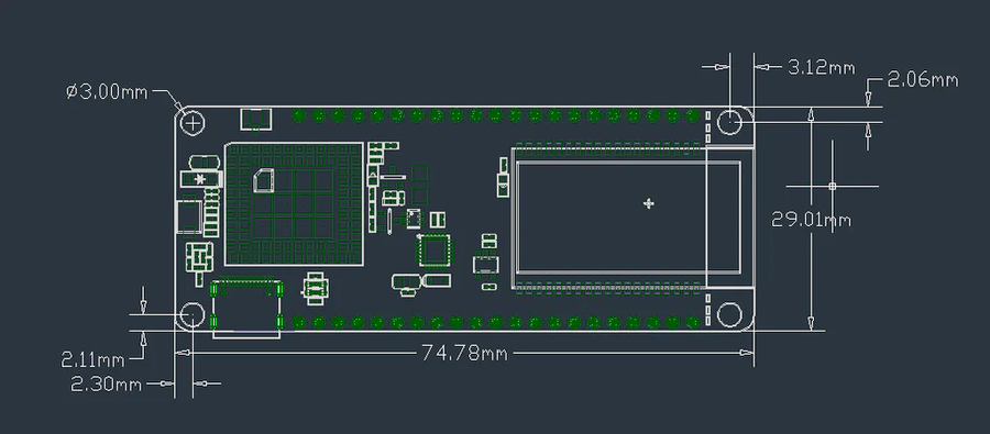
TTGO T-Call Cellular Modules Available Models SIM800H: 2G GSM/GPRS module supporting quad-band GSM (850/900/1800/1900MHz) and GPRS data transmission A7670E: LTE Cat.1 module with global LTE bands, ideal for IoT applications requiring higher data speeds SIM800L: Compact 2G module option for basic cellular connectivity Important Notes The A7670E module has LTE band limitations in some regions (e.g., US LTE…
TTGO T-Call Cellular Modules
Available Models
- SIM800H: 2G GSM/GPRS module supporting quad-band GSM (850/900/1800/1900MHz) and GPRS data transmission
- A7670E: LTE Cat.1 module with global LTE bands, ideal for IoT applications requiring higher data speeds
- SIM800L: Compact 2G module option for basic cellular connectivity
Important Notes
The A7670E module has LTE band limitations in some regions (e.g., US LTE bands may not be fully supported). Check cellular band compatibility for your location. SIM800H provides reliable 2G connectivity but limited data speeds.
Perfect For
Ideal for remote monitoring, asset tracking, smart agriculture, and any IoT project requiring cellular connectivity with WiFi/Bluetooth backup options.
Specifications
ESP32 · 51.52 × 25.04 mm · vs other ESP32 chips →Dimensions
About this board
At its core is the ESP32 - a dual-core Xtensa with both Bluetooth Classic and BLE.
Expect to pay about $26.52 - above the ~$20 typical for ESP32 boards.
Onboard you'll find 8MB (QSPI) PSRAM, cellular connectivity (SIM800L), battery charging (IP5306) via JST-PH 2.0 and Reset/Power buttons.
The TTGO T-Call is a powerful ESP32 development board designed for cellular IoT applications, featuring integrated GSM/GPRS connectivity alongside Wi-Fi 802.11 b/g/n and Bluetooth 4.2 + BLE.
Powered by an ESP32 dual-core processor at 240 MHz, with 4MB/8MB flash memory and 8MB PSRAM, it's optimized for demanding IoT projects requiring reliable remote connectivity.
The board features a SIM800L 2G GSM/GPRS modem for cellular communication (sibling T-Call boards use the SIM800H or the 4G A7670E). It includes a nano SIM card slot, GSM antenna connector, and comprehensive cellular interfaces.
Features USB Type-C for programming, Li-Po battery support with charging circuit, and extensive GPIO pins supporting ADC, DAC, PWM, I2C, SPI, UART, I2S, and CAN interfaces. Operating at 3.3V with robust power management.
- Cellular Connectivity
- Li-Po Battery Support
- Nano SIM Slot
- ESP32-WROVER-B with 8MB PSRAM
- u.FL (IPEX) GSM antenna connector
Where to buy
prices are typical street pricesResources
Similar boards


