
uPesy ESP32 Wroom DevKit
General-purpose ESP32 board with WROOM module - compact and easy to integrate into embedded projects.

uPesy ESP32 Wroom DevKit Pinout
15 pins · 2.54 mm pitch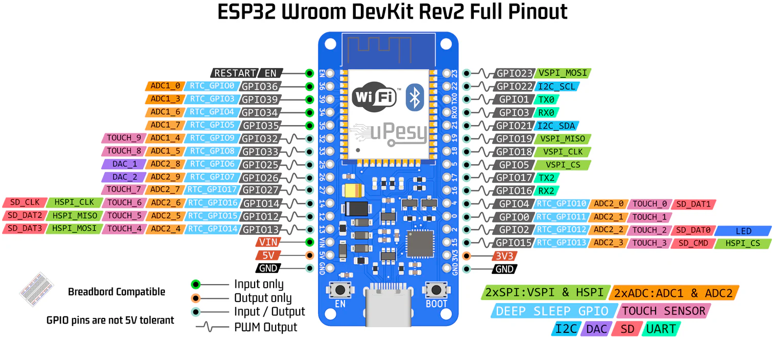
| Pin | GPIO | Labels | Status | Capabilities | Notes |
|---|---|---|---|---|---|
| 1 | 13 | LED_BUILTINGPIO13 | strapping | - | Built-in LED |
| 2 | 3 | IO3GPIO3 | uart | uart | UART Receive |
| 3 | 1 | IO1GPIO1 | uart | uart | UART Transmit |
| 4 | 21 | IO21GPIO21 | safe | i2c | I2C Data Line |
| 5 | 22 | IO22GPIO22 | safe | i2c | I2C Clock Line |
| 6 | 5 | IO5GPIO5 | strapping | spi | SPI Slave Select |
| 7 | 23 | IO23GPIO23 | safe | spi | SPI Master Out Slave In |
| 8 | 19 | IO19GPIO19 | safe | spi | SPI Master In Slave Out |
| 9 | 18 | IO18GPIO18 | safe | spi | SPI Clock Line |
| 10 | 36 | IO36GPIO36 | strapping | adc | ADC1 Channel 0 |
| 11 | 39 | IO39GPIO39 | strapping | adc | ADC1 Channel 3 |
| 12 | 32 | IO32GPIO32 | safe | adc | ADC1 Channel 4 |
| 13 | 33 | IO33GPIO33 | safe | adc | ADC1 Channel 5 |
| 14 | 25 | IO25GPIO25 | safe | - | Digital-to-Analog Converter 1 |
| 15 | 26 | IO26GPIO26 | safe | - | Digital-to-Analog Converter 2 |
Start with these
9 pins with no boot or system involvementFreely assignable - no strapping, flash, USB or JTAG duties. Ideal first picks for buttons, sensors and LEDs.
Fine - with a little care
6 pins · 6 things to knowLED_BUILTINGPIO13 JTAG clock pin (TCK); also ADC2 channel 4 / Touch4 input. JTAG
Used for JTAG debugging (TCK); avoid using as GPIO if JTAG is needed.
IO3 Default UART0 RX pin for USB-serial programming (console input). UART
Used for receiving data from USB-UART (programming); also pulled HIGH at boot for console communication, so using as GPIO can disrupt uploads.
IO1 Default UART0 TX pin for USB-serial programming and console. UART
Connected to on-board USB-UART for uploading and logs; drives serial output at boot, so using as GPIO can disrupt programming or console.
IO5 Bootstrapping pin; internal pull-up; VSPI CS0 (default SPI chip-select); acts as FSPIWP (flash write-protect) on internal-flash variants. Strapping
Must be HIGH during boot; if pulled LOW at reset, alters SDIO slave timing and may prevent normal boot.
IO36 Input-only GPIO (no output); ADC1 channel 0, Hall sensor VP. Other
Cannot be used as output; only suitable for input (e.g., analog read).
IO39 Input-only GPIO (no output); ADC1 channel 3, Hall sensor VN. Other
Cannot be used as output; only suitable for input.
All 15 pins on the uPesy ESP32 Wroom DevKit are usable GPIO, spaced at the standard 2.54 mm pitch.
Beyond plain digital I/O you get 4 ADC-capable pins for sensors and battery monitoring.
6 of the exposed pins carry boot-time or system duties on the ESP32 (LED_BUILTIN, IO3, IO1 and 3 more) - check the guidance above before wiring anything to them. IO21, IO22, IO23, IO19 and 5 more are free of any such role - the safest first picks.
Pinout notes The ESP32-WROOM DevKit provides a comprehensive and flexible pinout layout, making it an ideal choice for a wide range of IoT applications. The module includes…
The ESP32-WROOM DevKit provides a comprehensive and flexible pinout layout, making it an ideal choice for a wide range of IoT applications. The module includes a built-in LED connected to GPIO13, which can be easily controlled for status indicators or debugging. Communication is well-supported with dedicated pins like GPIO3 for UART receive and GPIO1 for UART transmit, ensuring seamless serial communication with other devices or computers.
For I2C communication, the board features GPIO21 for SDA and GPIO22 for SCL, allowing the connection of peripherals like sensors and displays. The SPI interface is equally robust, with GPIO23 for MOSI, GPIO19 for MISO, GPIO18 for SCK, and GPIO5 for the SS (Slave Select) line. These pins enable high-speed communication with external devices such as memory modules or other microcontrollers.
The board also supports multiple analog inputs through its ADC channels, with pins like GPIO36 (A0), GPIO39 (A3), GPIO32 (A4), and GPIO33 (A5). These pins are perfect for interfacing with sensors that provide analog output, such as temperature or light sensors. Additionally, it features two DAC outputs on GPIO25 (DAC1) and GPIO26 (DAC2), which allow for digital-to-analog signal conversion for applications like audio or waveform generation.
Getting started
flash your first firmware in ~2 minutesBoard: ESP32 Dev Module Flash Size: 4MB (32Mb) Flash Mode: DIO Partition Scheme: Default 4MB with spiffs (1.2MB APP/1.5MB SPIFFS) Upload Speed: 921600
// toggle GPIO21 - wire an LED and resistor to it
void setup() {
  pinMode(21, OUTPUT);
}
void loop() {
  digitalWrite(21, HIGH); delay(500);
  digitalWrite(21, LOW);  delay(500);
}[env:uPesy_wroom]
platform = espressif32
board = esp32dev
framework = arduino
monitor_speed = 115200
upload_speed = 921600esp32dev - or type it after board =.esp32:
board: esp32dev
variant: esp32
framework:
type: esp-idf
# blink - GPIO21
output:
- platform: gpio
pin: 21
id: led_out
light:
- platform: binary
name: "LED"
output: led_outesp32dev (same ids as PlatformIO).esptool.py --chip esp32 --port /dev/ttyACM0 \
--baud 921600 write_flash 0x1000 firmware.bin--port = your /dev/tty* (macOS/Linux) or COMx (Windows).Specifications
ESP32 · 57.7 × 27.5 mm · vs other ESP32 chips →Dimensions
About this board
Inside sits the ESP32 - a dual-core Xtensa with both Bluetooth Classic and BLE.
At $15.99 it's cheaper than most ESP32 boards, which usually run around $20.
Only 15 GPIO are broken out, where most ESP32 boards manage about 24 - worth checking the pinout covers what you need.
Around the module: status LEDs (Power, User (GPIO13)) and Reset/Boot buttons.
Where to buy
prices are typical street pricesResources
Similar boards


