
KY-019 5V Relay Module
The KY-019 is a 5V relay module that enables microcontrollers to control high-voltage devices. It supports both AC and DC loads, making it suitable for various automation and control applications.

KY-019 pinout
The KY-019 is a 3-pin 5V relay module for high-voltage/current switching:
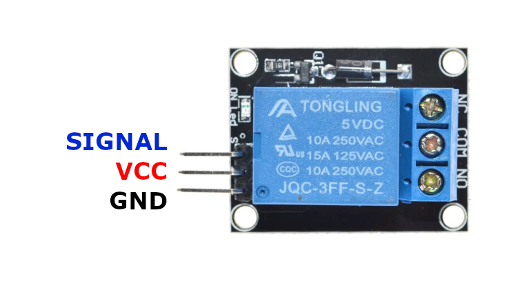
| Pin | Type | Description | Notes |
|---|---|---|---|
| Pin (-) | Power | Ground connection | |
| Pin (+) | Power | Power supply | 5V required for relay coil |
| Pin (S) | Control | Control signal input | HIGH to activate relay |
Interface: Digital control (relay switching)
Relay: Single-channel with NO (normally open) and NC (normally closed) contacts
Power: 5V coil voltage required
Capacity: AC 250V/10A or DC 30V/10A switching
LED: Onboard status indicator (lights when active)
Applications: Home automation, appliance control, motor control, light switching
Wiring the KY-019 to ESP32
To interface the KY-019 with an ESP32 for relay control:
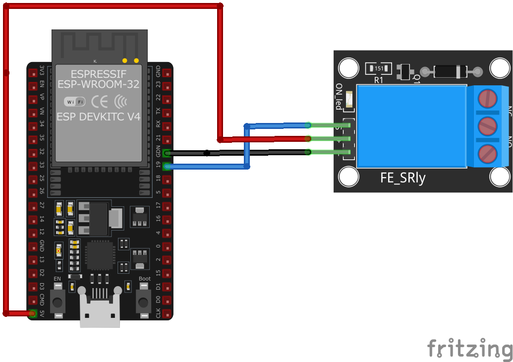
| KY-019 pin | ESP32 pin | Purpose |
|---|---|---|
| Pin (-) | GND | Ground |
| Pin (+) | 5V | Power supply (5V required) |
| Pin (S) | GPIO5 | Control signal (any GPIO) |
Control: Set GPIO HIGH to activate relay, LOW to deactivate
GPIO Selection: Any digital GPIO pin works, GPIO5 is just an example
5V Required: Relay coil needs 5V - ESP32’s 3.3V may not be sufficient
Load Wiring: Connect high-voltage load to NO/NC/COM terminals on relay
High Voltage: Use proper safety precautions when working with AC mains
KY-019 code examples
int relayPin = 5; // Relay signal pin (GPIO5, matches the wiring above)

void setup() {
    pinMode(relayPin, OUTPUT);
    Serial.begin(115200);
    Serial.println("KY-019 Relay Module Test");
}

void loop() {
    digitalWrite(relayPin, HIGH); // Turn relay on
    Serial.println("Relay is ON");
    delay(1000);
    digitalWrite(relayPin, LOW); // Turn relay off
    Serial.println("Relay is OFF");
    delay(1000);
}
The relay's signal pin connects to GPIO5 (matching the wiring above) and is simply toggled with digitalWrite() - HIGH energises the coil, LOW releases it, once per second in this test. Power the relay module from 5V (VIN) and remember the switched load side is electrically separate from the ESP32.
#include <stdio.h>
#include "freertos/FreeRTOS.h"
#include "freertos/task.h"
#include "driver/gpio.h"

#define RELAY_PIN GPIO_NUM_5

void app_main(void) {
    gpio_config_t io_conf = {
        .pin_bit_mask = (1ULL << RELAY_PIN),
        .mode = GPIO_MODE_OUTPUT,
        .pull_up_en = GPIO_PULLUP_DISABLE,
        .pull_down_en = GPIO_PULLDOWN_DISABLE,
        .intr_type = GPIO_INTR_DISABLE
    };
    gpio_config(&io_conf);

    printf("KY-019 Relay Module Test\n");

    while (1) {
        gpio_set_level(RELAY_PIN, 1); // Turn relay on
        printf("Relay is ON\n");
        vTaskDelay(pdMS_TO_TICKS(1000)); // Wait for a second
        gpio_set_level(RELAY_PIN, 0); // Turn relay off
        printf("Relay is OFF\n");
        vTaskDelay(pdMS_TO_TICKS(1000)); // Wait for a second
    }
}
This ESP-IDF code configures GPIO5 as an output to control the KY-019 relay module. It toggles the relay state every second, turning it on and off, while printing the status to the console.
switch:
  - platform: gpio
    pin: GPIO5
    name: "KY-019 Relay"
    icon: "mdi:relay"
    restore_mode: ALWAYS_OFF
This ESPHome configuration sets up the KY-019 relay module on GPIO5 as a switch. The relay can be controlled from Home Assistant and will always start in the OFF state when powered up.
[env:esp32]
platform = espressif32
board = esp32dev
framework = arduino#include <Arduino.h>
#define RELAY_PIN 5
void setup() {
pinMode(RELAY_PIN, OUTPUT);
Serial.begin(115200);
Serial.println("KY-019 Relay Module Test");
}
void loop() {
digitalWrite(RELAY_PIN, HIGH);
Serial.println("Relay is ON");
delay(1000);
digitalWrite(RELAY_PIN, LOW);
Serial.println("Relay is OFF");
delay(1000);
}This PlatformIO code configures GPIO5 as an output for the KY-019 relay module. The relay toggles ON and OFF every second, with the status printed to the serial monitor.
import machine
import time

RELAY_PIN = machine.Pin(5, machine.Pin.OUT)

while True:
    RELAY_PIN.value(1)
    print("Relay is ON")
    time.sleep(1)
    RELAY_PIN.value(0)
    print("Relay is OFF")
    time.sleep(1)
This MicroPython script configures GPIO5 as an output to control the KY-019 relay module. The relay turns ON and OFF every second, with messages printed to the console.
KY-019 specifications
About the KY-019
The KY-019 wraps a 5V, 10A SPDT relay behind an NPN transistor driver with a flyback diode across the coil, so the signal pin isn’t switching the mains-rated contacts directly - it’s just biasing a small transistor that does the real work, and the diode absorbs the coil’s turn-off spike so it doesn’t feed back into the GPIO. The catch is in the module’s own spec sheet: it calls for a 5-12V TTL control signal, not 3.3V, and while plenty of ESP32 projects do trigger it fine straight off a 3.3V GPIO, individual boards and transistor batches can switch marginally or not at all at that voltage - worth testing before wiring one into anything unattended, with a logic-level buffer or a relay board designed for 3.3V as the safer fallback if it doesn’t trigger reliably.
The relay contacts themselves are rated 250VAC/10A and 30VDC/10A, plenty for switching mains-powered devices, but that’s exactly where the real danger shifts from the electronics to the wiring: mains connections belong on the NO/NC/COMMON screw terminals only, kept fully separated from the low-voltage side and properly insulated. A mistake on the low-voltage side blows a GPIO; a mistake on the high-voltage side is a shock or fire risk, so leave that wiring to someone comfortable working with line voltage.
KY-019 troubleshooting
Relay Not Activating
›
Issue: The relay does not switch when the control signal is applied.
Solutions:
- Ensure the control signal voltage is 5V; the relay may not activate with lower voltages.
- Verify that the
Pin (+)is connected to a stable 5V power source. - Check for proper grounding between the module and the microcontroller.
Unstable Relay Operation
›
Issue: The relay switches intermittently or unpredictably.
Solutions:
- Ensure that the power supply can provide sufficient current for the relay.
- Check for loose connections or faulty wiring.
- Confirm that the control signal is not experiencing noise or interference.
Where to buy the KY-019

Resources
Similar sensors


