
ESP-LED-01 - DIY ESP32-S3 Sound Reactive WLED Controller
Build your own ESP-LED-01 WLED controller with an ESP32-S3 SuperMini. Features sound reactivity, auto brightness via light sensor, and clean 5V LED control.
When I started this project, my goal was to build a custom WLED controller that could handle sound-reactive effects and automatically adjust brightness based on ambient light. A lot of controllers out there either have one feature or the other, but rarely both cleanly integrated. This is the first version of the controller, and while it already works great, there’s a v2 in development that will add an IR receiver and expose more free GPIOs for additional expansions.
At the heart of this board is the ESP32-S3 SuperMini, which offers a lot more performance compared to the ESP32-C3 SuperMini variants, mainly thanks to its dual-core architecture. This extra processing power really helps with fast, reliable sound-reactive LED effects without bogging down the controller.
Planning the Circuit #
Before jumping straight into making a PCB, I wanted to be sure the design actually worked the way I imagined. So, like any good project, it started with some breadboarding, a lot of jumper wires, and a little bit of chaos.
I picked the ESP32-S3 SuperMini as the brain of the controller. It’s super compact and cheap but still really powerful - the dual-core S3 handles both the WiFi stack and the real-time audio processing without even breaking a sweat.
For the sound reactivity, I went with the INMP441 digital MEMS microphone. I specifically wanted something digital to avoid the noise issues that come with analog mics, especially when you're dealing with a messy breadboard setup. It’s small, sensitive, and hooks up via I2S - perfect for WLED’s audio input.
Since I also wanted the lights to automatically dim when the room gets darker, I added a simple light sensor - just an LDR (photoresistor) wired with a pull-down resistor. Nothing fancy here, but it integrates nicely into WLED’s auto-brightness features.
Another important piece was the 74AHCT125N level shifter. While addressable LED strips like the WS2812B can sometimes work directly with the ESP32’s native 3.3V data output, it's not reliable or recommended - especially for longer strips or more complex animations. These LEDs expect a clean 5V logic signal to latch data correctly. The 74AHCT125N steps up the 3.3V signal properly, ensuring the first LED in the chain picks up the data every time, even over longer runs.
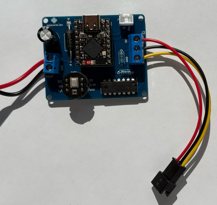
Finally, to keep wiring clean and ready for real-world installs, I added a 2-pin terminal block for power input and a 3-pin terminal block for connecting to the LED strip: +5V, Data, and GND.
Fritzing Diagram: Visual layout of the initial breadboard circuit
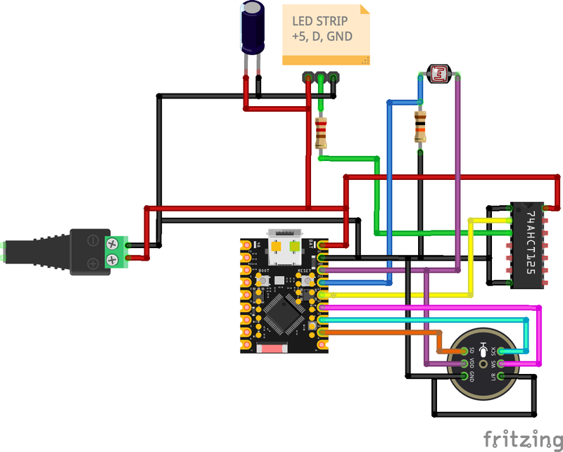
In this wiring:
- Power flows from the barrel jack to the terminal blocks and to the ESP32-S3 SuperMini.
- 🟣 INMP441 Mic connects to the ESP’s I2S pins.
- ⚪ Light Sensor connects to an analog GPIO input, with a pull-down resistor to ensure a clean, stable reading when idle.
- 🟠 74AHCT125N is wired to shift the ESP’s data output to the required 5V levels for the LED strip.
- ⚫ Capacitor placed across the power lines near the LED strip connection to smooth out voltage dips during heavy loads.
- 🟤 Resistor in series with the data line before the strip to improve signal integrity and protect the first pixel.
This setup worked well for initial firmware flashing and feature testing, and gave me confidence to move on to PCB design.
Building a Prototype on a Breadboard #
Honestly, I was too excited about the project to wait for the PCB to arrive, so I built everything out on a breadboard first. It worked out great - getting hands-on early helped me tweak a few small things before committing to a final board. But about that, a little bit later.
Here’s how I approached the breadboard build:
- Assembled the full circuit on a breadboard, following the planned schematic.
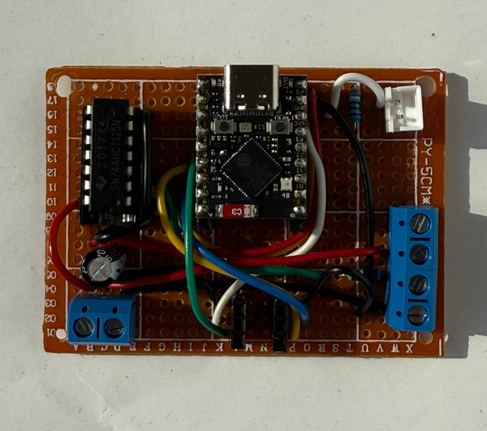
- Flashed an initial build of WLED onto the ESP32-S3 SuperMini and ran quick tests on the LED strip to verify everything was working correctly.
- Tested each critical part separately - making sure the INMP441 microphone picked up clean audio, the 74AHCT125N pushed out a proper 5V signal, and that power delivery stayed solid even under heavier loads.

Prototyping everything first ended up saving a ton of time and let me keep building without having to wait around.
Designing and Ordering the PCB #
After validating everything on the breadboard, I started working on the PCB. Building the prototype helped highlight a few key improvements I wanted baked into the final version.
On the protection side, I added a Schottky diode for reverse voltage protection, rated for up to 5A - because accidents happen. I also placed a big electrolytic capacitor across the LED power lines to help absorb current spikes when lots of LEDs switch on at once. To protect the data line, I included a small series resistor (around 330Ω) right before the LED strip connection, helping to prevent voltage overshoot from damaging the first pixel.
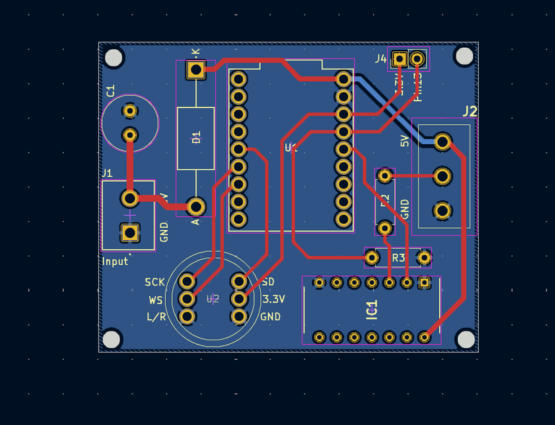
For designing the PCB, I used KiCad. (You could just as easily use EasyEDA or similar tools - whatever you’re comfortable with.) A few things I kept in mind specifically for a WLED controller:
- Power traces need to be wide enough to handle the LED current without heating up - even if it looks oversized, extra copper is always better.
- Signal traces (like the microphone and light sensor lines) should be routed cleanly and kept away from noisy power lines whenever possible.
- The level shifter output to the LEDs got short, direct traces to minimize the chance of signal reflections.
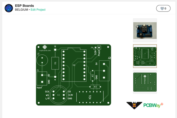
Once the layout was done, I exported the Gerber files and uploaded them straight to PCBWay for manufacturing. Their quick turnaround made it easy to keep the project moving without losing momentum.
Order Your Own PCB #
If you want to build your own version of this WLED controller, you can order the professionally manufactured PCB through PCBWay:
👉 Order the WLED Controller PCB on PCBWay
PCB Assembly #
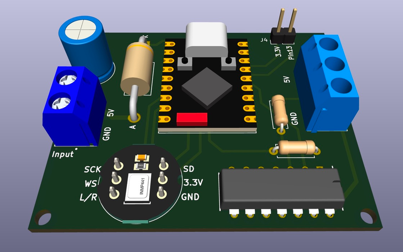
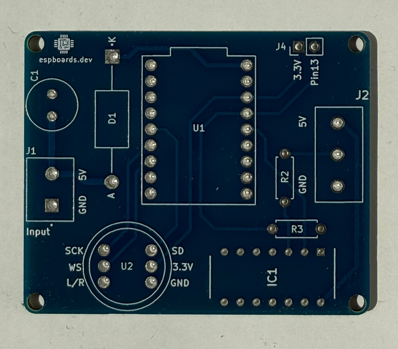
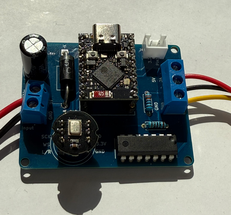
After a bit of a wait (and overly checking the production and tracking info), the PCBs finally arrived from PCBWay! Opening the package was super exciting - there’s nothing quite like seeing a design you worked on digitally turn into a real, physical board.
Bill of Materials (BOM) #
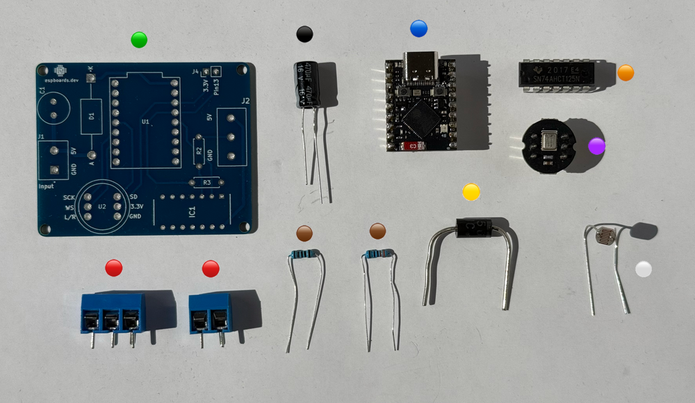
Before diving into soldering, I laid out all the components on the bench, making sure everything matched my design checklist. Here’s the complete Bill of Materials (BOM) for this WLED controller:
| Color | Image | Name | Description | Affiliate / Purchase Link |
|---|---|---|---|---|
| 🟢 |  | PCB | Freshly manufactured PCB (ordered from PCBWay) | PCBWay Project Link |
| 🔵 |  | ESP32-S3 SuperMini | Main controller, dual-core ESP32-S3 with USB support |  |
| 🟣 |  | INMP441 MEMS Microphone | Digital MEMS mic breakout for clean, noise-free I2S sound input |   |
| 🟠 |  | 74AHCT125N | Logic level shifter to bump 3.3V data up to 5V for addressable LEDs | |
| ⚪ |  | Light Sensor (LDR5516) | Connects to an analog GPIO input, with a pull-down resistor to ensure a clean, stable reading when idle | |
| 🔴 |  | 2-pin Terminal Block | Power input connection | |
| 🔴 | | 3-pin Terminal Block | LED strip output (+5V, Data, GND) connection | |
| ⚫ |  | Big Electrolytic Capacitor | 470uF or similar, rated for 6.3V or higher, stabilizes power | |
| 🟡 |  | Reverse Voltage Protection Diode | Diode capable of handling up to 5A (e.g., SR260) | |
| 🟤 |  | Series Data Resistor | 330–470 ohms, protects the first LED pixel from signal spikes | |
Double-checking against the BOM before soldering really saved a ton of headaches - no last-minute surprises or missing parts once the iron was hot.
Soldering Guide #
When it came time to actually assemble the board, I found it easiest (and safest) to solder the components in a specific order, starting with the flattest parts first. Here's how I did it:
- 🟤 Resistors: These are the smallest and sit right against the board, so they went in first. Quick to place, quick to solder.
- 🟠 74AHCT125N Level Shifter: Next up was the level shifter IC. I carefully lined it up with the pads and tacked two opposite corners before soldering all the pins cleanly.
- 🟡 Diode: Important for reverse voltage protection - just make sure to double-check the polarity before soldering.
- 🟣 INMP441 Microphone (or a header socket, if you want it to be replaceable): Because of its tiny size, I took extra care here. A set of helping hands or tweezers really helps with positioning.
- 🔵 ESP32-S3 SuperMini (or a header socket for easy swapping): I chose to solder mine directly to keep the profile low, but using a socket is a great option if you want to swap out or update the ESP later.
- 🔴 Terminal Blocks: The 2-pin and 3-pin terminal blocks are a bit chunky, so it made sense to add them after all the small parts were done. This way, they don't get in the way while soldering.
- ⚫ Capacitor: I saved the big electrolytic capacitor for last. Since it's pretty tall, soldering it at the end kept everything easy to access during the earlier stages.
Tip:
If you're building this yourself, take your time and work systematically. After placing each major part, it’s a good idea to do a quick visual inspection - making sure everything’s seated properly and that there are no accidental solder bridges. It’s way easier to catch mistakes early than after the whole board is populated.
Instead of mounting the light sensor directly onto the PCB, I added a JST connector.
The reason is simple: ambient light can vary a lot depending on where the controller is physically installed. By using a connector, I can:
- Extend the light sensor away from the board to a better, more exposed location.
- Optimize brightness control by placing the sensor where it actually detects room lighting conditions accurately (not inside an enclosure or hidden behind furniture).
For the ESP32-S3 SuperMini and the INMP441 microphone, I decided to use female header sockets instead of soldering them directly.
The main advantages:
- Easy Replacement: If something happens to the ESP32 or mic (e.g., static damage, future upgrades), I can swap them out without any desoldering.
- Flexible Testing: While developing and flashing firmware, it’s much easier to remove the ESP32-S3 for reprogramming or debugging.
| Image | Name | Description | Affiliate / Purchase Link |
|---|---|---|---|
 | Series Data Resistor | 330–470 ohms, protects the first LED pixel from signal spikes | |
It’s a small design choice, but it makes the whole setup way more serviceable and future-proof.
Of course, if you prefer, you can directly solder the ESP32-S3 SuperMini and the microphone module to the board for a more compact and permanent installation.
Verifying Connections #
Once everything was soldered, I didn’t immediately plug in power - first, I did a quick round of checks with a multimeter:
- Continuity checks between VCC and GND (no shorts!)
- Checking that the diode is properly blocking reverse voltage
- Verifying connections from the ESP32 to the microphone, light sensor input, and LED data line
Everything looked good on the meter, which meant it was finally time to power it up for real and move on to flashing WLED!
Installing and Configuring WLED #
With the board fully assembled and tested for basic continuity, it was finally time for the fun part: flashing WLED onto the ESP32-S3 SuperMini and setting everything up!
Flashing WLED to the ESP32-S3 SuperMini #
First, I grabbed the latest WLED build that supports the ESP32-S3 architecture. You can either compile it yourself using PlatformIO or Arduino IDE, or just grab a precompiled .bin from WLED’s nightly builds (make sure it’s a build with S3 support!).
I used the WLED Web Installer for quick flashing:
- Plugged the ESP32-S3 SuperMini into my computer via USB-C.
- Opened install.wled.me in Chrome.
- Selected the correct COM port and started flashing.
It took just a couple of minutes. Once flashing was complete, the ESP rebooted and created a Wi-Fi network for initial setup.
Tip: If flashing fails, check if you need to hold down the boot button (depending on your SuperMini version).
Configuring LED Settings #
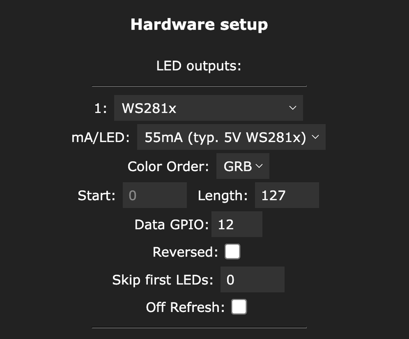
- Navigate to LED Preferences in WLED.
- Under Hardware setup, set the Data GPIO to 12.
Configuring the Microphone Input for Sound Reactivity #
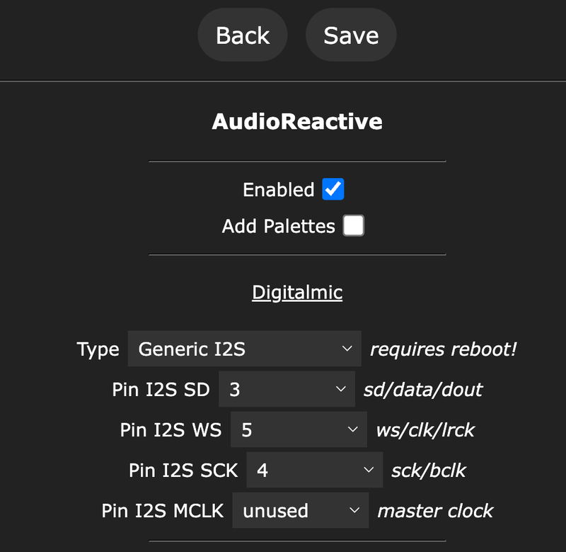
- Navigate to Usermods in WLED.
- Under AudioReactive, set the audio input to Generic I2S.
- Configure these pins:
- Pin I2S SD: 3
- Pin I2S WS: 5
- Pin I2S SCK: 4
The INMP441 mic was surprisingly sensitive - even moderate background music triggered awesome visual effects!
Testing Signal Output to the Addressable LED Strip #
Finally, it was time to hook up the LED strip:
- Connected the 3-pin output terminal to my WS2812B strip: 5V, Data, GND.
- Selected a few test effects from WLED’s preset list.
Success! The LEDs lit up perfectly, the sound-reactive patterns pulsed to music, and brightness adjusted smoothly with changing light levels.
Extra Step: I also used a multimeter to check that the data signal at the strip input was a clean 5V thanks to the 74AHCT125N level shifter - it definitely makes a difference for reliable LED operation.
Bonus #
While this first version of the WLED controller already covers sound reactivity and automatic brightness pretty nicely, there's always room for improvement. As soon as I saw everything working, I started thinking about upgrades for v2!
Future Upgrades #
IR Receiver Port:
One of the biggest features planned for the next version is adding an IR receiver. This would allow remote control of the lights without needing Wi-Fi - perfect for quick adjustments, party modes, or just turning the lights off from across the room.Exposing Extra GPIOs:
In the next version, the extra GPIOs will be broken out cleanly to headers or small connectors, making it easy to:- Add buttons (for mode switching or brightness control)
- Hook up additional sensors (like temperature, motion, etc.)
- Expand to multiple light outputs with software tweaks
The idea is to keep the board flexible: even though it’s built around WLED, having extra GPIOs available means it could easily be adapted for custom firmware or future versions of WLED that add more features.
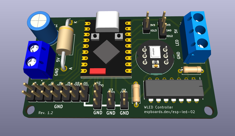
Here's a little sneak peek of what's coming in v2 - the design is already underway! 🚀
Conclusion #
This custom WLED controller project started as a simple idea - a sound-reactive, auto-brightness LED controller - and turned into a solid, fully working PCB that's ready for real-world setups.
To recap, this first version includes:
- An ESP32-S3 SuperMini as the powerhouse, offering dual-core performance and easy USB flashing.
- INMP441 digital microphone support for smooth sound-reactive effects.
- Light sensor input for automatic brightness adjustment.
- A 74AHCT125N level shifter to reliably drive addressable LED strips.
- Reverse voltage protection with a diode rated for up to 5A.
- Clean, easy-to-wire 2-pin and 3-pin terminal blocks for power and LEDs.
If you want to build your own or just check it out, the PCB is available to order from PCBWay - it’s a great way to get a clean, compact setup for your next LED project!
Order Your Own PCB #
If you want to build your own version of this WLED controller, you can order the professionally manufactured PCB through PCBWay:
👉 Order the WLED Controller PCB on PCBWay
Also, if you're interested in more ESP32-S3 related builds or deep dives into WLED setups, make sure to check out:
- The ESP32-S3 SuperMini Board page for more technical details and other project ideas.
More updates coming soon, especially once v2 of this controller is ready!