
ESP-LED-02 - DIY ESP32-S3 Full Featured WLED Controller
Updated ESP-LED-02 WLED controller with an ESP32-S3 SuperMini featuring THT components, sound reactivity, IR control, a light sensor, and clean 5V LED output.
As already mentioned in the ESP-LED-01 WLED controller, it was clear there were a few things that could take the build to the next level. While the first version already handled sound reactivity and auto-brightness really well, I wanted to make the design a bit more flexible, expandable, and stable - especially for users who want to customize their setups further.
That’s where ESP-LED-02 comes in. This version builds on everything from the original and adds:
- A dedicated port for an IR receiver, so you can control your LEDs with a remote.
- Extra GPIOs broken out, giving you access to unused pins on the ESP32-S3 SuperMini.
- A fix for the SN74AHCT125 level shifter - all unused channels now have their enable pins pulled HIGH to eliminate random blinking or signal noise.
If you’re building a more permanent WLED install, or you just want a little more control over your setup, this version should fit the bill.
What’s New in ESP-LED-02 #
1. Infrared Receiver Support #
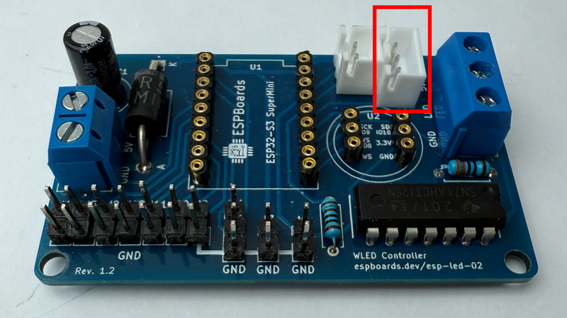
One of the most requested features after ESP-LED-01 was the ability to control the LEDs with a remote - especially for quick brightness changes or mode switching when Wi-Fi isn’t convenient. ESP-LED-02 now includes a dedicated header for an IR receiver module, like the TSOP38238.
This plugs directly into the board and integrates with WLED’s built-in IR support. Once connected and enabled in WLED, you can control effects, brightness, and power using a standard IR remote (like the classic 24-key or 44-key models).
To ensure stable operation, the header includes an optional pull-up resistor on the IR signal line. You can also add a small decoupling capacitor near the IR module for better signal stability, especially in noisy environments or longer cable runs.
2. Free GPIOs for Expansion #
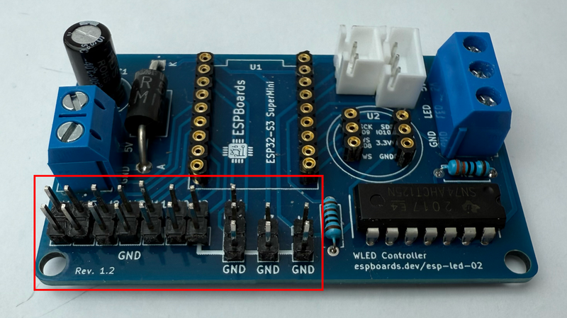
One limitation of the original board was that it didn’t expose many GPIOs, making expansion or customization a bit of a hack. ESP-LED-02 fixes that - it now breaks out GPIOs 1 through 7 to a clearly labeled header, along with TX, RX, 3.3V, 5V, and GND.
This opens up a ton of new possibilities:
- Add buttons for cycling effects or toggling power without using a phone or remote.
- Connect a motion sensor for reactive lighting.
- Add a second light sensor or temperature sensor.
- Use advanced WLED usermods to control multiple LED strips or other peripherals.
If you're adding extra inputs or building your own custom logic, this GPIO access makes the board way more versatile without needing to rework the PCB.
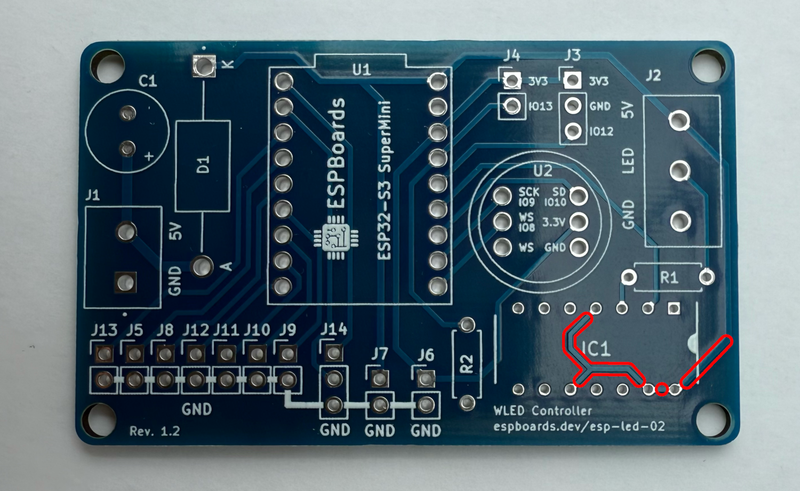
3. SN74AHCT125 Level Shifter Fixes #
In the original version, only one channel of the SN74AHCT125 was used to shift the LED data signal up to 5V. The remaining unused channels had their enable (EN) pins left floating, which sometimes caused unexpected behavior - random flickering or ghost signals, especially at power-up.
ESP-LED-02 addresses this by explicitly tying all unused EN pins to HIGH, disabling those channels entirely. This small fix significantly improves signal stability, especially when powering up or resetting the controller.
It's a subtle hardware refinement, but it removes one more potential source of glitches and makes the whole setup more robust.
Updated Circuit Design #
Compared to the original ESP-LED-01, the schematic for ESP-LED-02 is a refinement - not a total overhaul. The core components are still in place: the ESP32-S3 SuperMini as the controller, the INMP441 for audio input, the LDR for ambient light sensing, and the SN74AHCT125 for proper 5V LED signaling.
Important Note: Because of the reorganized GPIO layout in ESP-LED-02, you'll need to update your WLED pin configuration compared to v1:
- LED Data Pin is now on GPIO 11 (was GPIO 12 in v1).
- I2S Microphone (INMP441) pins:
- SCK → GPIO 6
- WS → GPIO 5
- SD → GPIO 10
- Light Sensor remains on GPIO 13
- IR Receiver connects to GPIO 12
These changes allow cleaner routing and make room for the new expansion header while keeping everything on stable, low-conflict pins. Just make sure to update your WLED hardware and usermod settings accordingly when setting up the new board.
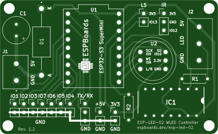
Revised PCB Layout #
Designing the PCB for ESP-LED-02 was all about refining the layout to make it more practical for real-world builds - if you're putting it inside an enclosure or mounting it in a fixed installation.
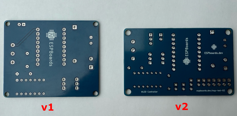
The new layout was again done in KiCad, and while it follows the same overall footprint as v1, there are several improvements worth highlighting:
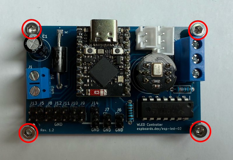
Mounting Holes #
The updated design features precisely sized mounting holes that now fit standard M3 screws perfectly. If you're installing the board in an enclosure or securing it to a panel, you can count on a snug, reliable fit without the need for washers or modifications. This small but important update makes installation faster and more secure.
More Organized GPIO Routing #
With GPIOs 1 through 7 now exposed via a dedicated header, routing was adjusted to keep signal traces cleaner and shorter. The expansion header sits in a convenient spot along one side of the board, with all pins clearly labeled on the silkscreen. No need to reference a separate diagram while building - just plug in your sensors or buttons and go.
This also made internal routing more efficient. Power traces stay fat and low-resistance, and signal lines (especially I2S) avoid noisy zones.
Improved Silkscreen Labels #
One small but very welcome change: more helpful silkscreen labels. Every major component - from terminal blocks to headers and the level shifter - now has visible, legible text on the top layer. This makes soldering and testing way easier, especially if you’re building more than one unit.
Pin functions on the GPIO header are also clearly marked - no more guessing which pad is RX or 3V3.
IR Receiver Placement #
The IR header is placed near the edge of the board so you can easily run a cable or mount the receiver facing outward in an enclosure. If you're installing this under a desk, behind a TV, or inside a project box, you’ll be able to route the IR sensor somewhere with line-of-sight to your remote without needing long jumper wires or adapter boards.
Between the cleaned-up layout, extra labeling, and better component placement, ESP-LED-02 feels like a much more polished version - easier to build, easier to expand, and just cleaner overall.
Updated BOM (Bill of Materials) #
Most of the core components from ESP-LED-01 carry over directly into this revision, which means you can reuse parts if you're upgrading or building both versions side by side. That includes:
- ESP32-S3 SuperMini – the main controller.
- INMP441 MEMS microphone – still connected over I2S.
- LDR light sensor with pull-down resistor – same GPIO (IO13).
- SN74AHCT125N level shifter – now with updated EN pin handling.
- Big electrolytic capacitor, series data resistor, terminal blocks, and Schottky diode - all remain unchanged.
What’s New in ESP-LED-02 #
While most of the core is the same, ESP-LED-02 adds a few extra components to support the new features:
| Color | Image | Component | Purpose | Notes | Purchase Link |
|---|---|---|---|---|---|
| 🟩 |  | IR Receiver Module (TSOP38238 or similar) | Enables remote control | Optional, plugs into dedicated header |   |
| 🟦 |  | More Male Header Pins | GPIO breakout | For connecting external sensors, buttons, or extensions. 26 Pins Total. | |
 | Infrared Controller | 44-pin or Other IR Controller | Used for remote controlling the WLED | |
The nice part is that even with these additions, the board stays compact and affordable - you’re adding more flexibility without increasing the cost significantly.
Full ESP-LED-02 Bill of Materials (BOM) #
| Color | Image | Name | Description | Purchase Link |
|---|---|---|---|---|
| 🟢 |  | PCB | Freshly manufactured PCB (ordered from PCBWay) | PCBWay Project Link |
| 🔵 |  | ESP32-S3 SuperMini | Main controller, dual-core ESP32-S3 with USB support |  |
| 🟣 |  | INMP441 MEMS Microphone | Digital MEMS mic breakout for clean, noise-free I2S sound input | |
| 🟠 |  | 74AHCT125N | Logic level shifter to bump 3.3V data up to 5V for addressable LEDs | |
| ⚪ |  | Light Sensor (LDR5516) | Connects to an analog GPIO input, with a pull-down resistor to ensure a clean, stable reading when idle | |
| 🔴 |  | 2-pin Terminal Block | Power input connection | |
| 🔴 | | 3-pin Terminal Block | LED strip output (+5V, Data, GND) connection | |
| ⚫ |  | Big Electrolytic Capacitor | 470uF or similar, rated for 6.3V or higher, stabilizes power | |
| 🟡 |  | Reverse Voltage Protection Diode | Diode capable of handling up to 5A (e.g., SR260) | |
| 🟤 |  | Series Data Resistor | 330–470 ohms, protects the first LED pixel from signal spikes | |
| 🟩 | | Infrared Sensor | TSOP38238 or Similar | |
| 🟦 | | Male Header Pins | 2 x 7, 2 x 3, 3 x 2 or 26 Pins Total | |
| Infrared Controller | 44-pin or Other IR Controller | |
Assembling ESP-LED-02 #
If you've already built ESP-LED-01, the assembly process for v2 will feel familiar - just with a couple of new steps. The board layout is a bit more spacious in key areas, and there are new headers to populate if you plan to use the IR receiver or GPIO expansion.
Recommended Soldering Order #
To make things easier and avoid blocking access to smaller components, here’s the updated soldering sequence:
- 🟤 Resistors – Start with the smallest, lowest-profile parts.
- 🟠 SN74AHCT125N Level Shifter – Position carefully and tack down two opposite corners before finishing.
- 🟡 Diode – Make sure it’s oriented correctly for reverse voltage protection.
- 🟣 INMP441 Microphone – Either solder it directly or use a female header.
- 🟩 IR Receiver Header – Optional, but add it now if you're using IR control.
- 🔵 ESP32-S3 SuperMini – Direct solder or socket; same options as before.
- 🟦 GPIO Expansion Header – Add this if you plan to use external buttons or sensors.
- 🔴 Terminal Blocks – Power and LED connections; save them for near the end.
- ⚫ Big Capacitor – Last in, since it’s the tallest component.
Tips if You Built ESP-LED-01 #
- The overall footprint and pinout of the ESP32-S3 SuperMini remains unchanged - you can reuse flashing jigs or enclosures.
- GPIO assignments have moved around, so be sure to update your WLED configuration.
- Visually, the v2 board is easier to assemble thanks to improved silkscreen markings and better grouping of headers.
And as always, once assembled, do a continuity check on power and ground before plugging anything in!
Firmware Notes #
ESP-LED-02 still runs WLED, and flashing the firmware is exactly the same as v1.
Flashing WLED #
Use the WLED Web Installer or your preferred method:
- Plug in the ESP32-S3 via USB-C
- Go to install.wled.me
- Select the correct COM port and flash the latest ESP32-S3 compatible build
You can also build WLED yourself with custom usermods or preconfigure your settings if you're flashing multiple units.
If you need more detailed instructions, check the "Flashing WLED to the ESP32-S3 SuperMini" section in ESP32-LED-01 instructions or "Guide to Setting Up and Troubleshooting ESPHome on ESP32".
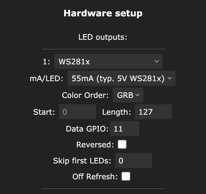
Updated Pin Configuration in WLED #
Since some GPIOs have changed in this version, here’s the updated mapping you’ll need to apply in WLED LED Preferences:
- LED Data Pin →
GPIO 11 - Light Sensor →
GPIO 13 - IR Receiver →
GPIO 12
For sound reactivity (I2S mic) in WLED Usermods:
- I2S SCK →
GPIO 6 - I2S WS →
GPIO 5 - I2S SD →
GPIO 10
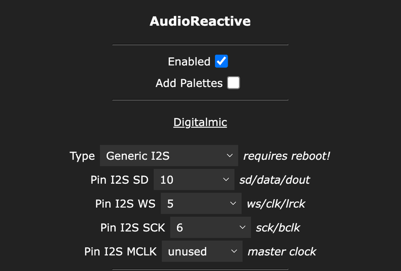
Update these under Usermods → AudioReactive and LED Preferences once WLED is running. With these set, ESP-LED-02 should behave just like v1 - but with more control and less hassle.
Infrared Control #
WLED supports control via IR remotes, allowing basic lighting operations without Wi-Fi or a smartphone. This is especially useful for quick on/off, brightness, effect, and color changes.
44-key Infrared Controller
Power On/Off
Brightness up/down
Static color selection
Dynamic effect modes
Speed and effect cycling
WLED has built-in support for this remote - no custom mapping needed in most cases.
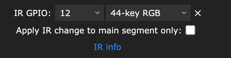
Simpy set IR GPIO in WLED LED Preferences:
- IR GPIO →
GPIO 12 - Type →
44-key RGB
👉 For more details on IR integration and supported remotes, see the WLED Infrared Interface Documentation.
Optional: Usermods with Extra GPIOs #
If you're using the newly exposed GPIOs for custom features (e.g., buttons, relays, additional LED outputs), you can assign them using WLED’s Usermods interface or modify the config in source code before flashing.
The new GPIO access is great for builders who want to take WLED further - whether that’s automating lighting scenes or building multi-zone effects.
Project Files & Ordering the PCB #
Once you're ready to build ESP‑LED‑02 yourself, everything you need is available for easy access:
- PCBWay project page – includes preview images, pricing options, and the “order now” button for manufacturing panels:
👉 ESP‑LED‑02 on PCBWay
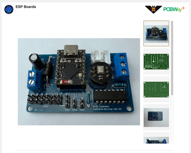
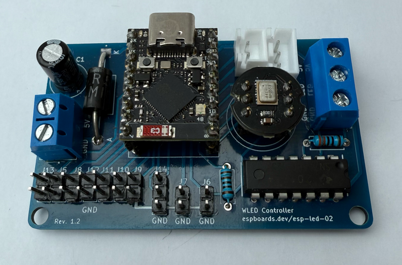
- Preview image of the assembled board – check the board’s layout and component placement before ordering:
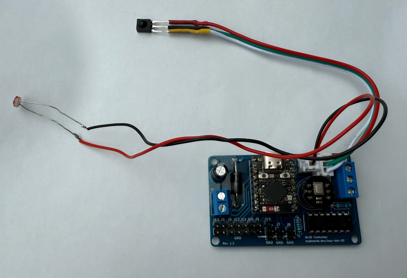
If you're ordering a single board for experimentation or building a small batch for multiple rooms, everything is packaged together for a streamlined build experience.
Future Thoughts #
ESP-LED-02 already covers a lot of ground - from sound reactivity and ambient brightness control to IR remote support and flexible GPIO expansion. But it’s also built with future upgrades in mind.
With the new breakout header and cleaner layout, this version offers a far more modular foundation for advanced WLED setups. Here are a few expansion ideas already on the radar:
🔋 Support for 12V / 24V LED Strips #
One of the most requested features is native support for higher voltage LED strips - especially 12V or 24V WS2811/2815 types. While ESP-LED-02 is still 5V-focused, a future revision (or daughterboard) could add:
- Onboard buck converter to power the ESP from higher voltages.
- Proper level shifting and power protection for 12V/24V compatibility.
This would open the door to longer strips, lower current draw, and simpler wiring for large installations.
⚡ External Power / Current Monitoring #
Another powerful addition would be integrating a current sensor (e.g., INA219 or INA3221) for real-time power tracking:
- Detect when your LED setup is drawing too much current.
- Enable WLED to auto-dim or warn you before overload.
- Log energy usage for smart home dashboards or power efficiency projects.
Thanks to the exposed GPIOs, adding this kind of sensor to ESP-LED-02 is already possible - and might even show up in ESP-LED-03 or as a plug-in module.
Closing #
ESP‑LED‑02 is more than just an incremental update - it’s a small evolution in how DIY WLED controllers can be built and expanded. By adding IR support, exposing more GPIOs, and cleaning up some of the small quirks from v1, this board becomes a more reliable, more flexible, and more install-friendly option for both casual and advanced builders.
Doensn't matter if you're using it to light up a room, sync with music at a party, or build a modular LED art piece, ESP‑LED‑02 gives you the features you need now - and a platform to grow on later.
If you end up building one, I’d love to see what you make! Tag or share your project photos, mods, or enclosures - and definitely let me know what features you'd love to see in ESP‑LED‑03. More voltage options? Built-in sensors? Custom enclosures? It's all up for grabs in the next round.
Stay tuned - and happy soldering!