ESP32 Obstacle Detection and Distance Measurement with IR Sensors
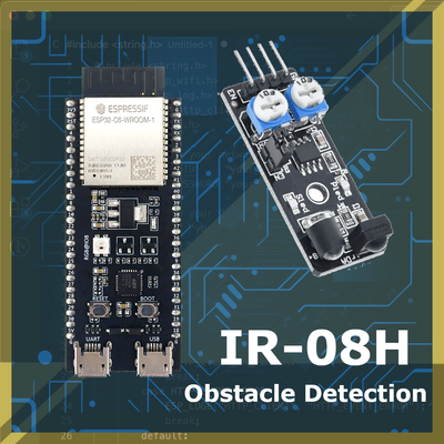
Explore how to set up IR sensors with ESP32. Learn about popular IR sensors such as IR-O8H, and discover how to use it for obstacle detection.
Obstacle Detection and Distance Measurement Using ESP32 and IR Sensors #
This guide provides an in-depth overview of using the ESP32 microcontroller with infrared (IR) sensors for obstacle detection and distance measurement. The project combines practical examples, wiring diagrams, and code to help you set up and test your ESP32 with common IR sensors.
What is Obstacle Detection? #
Obstacle detection is the process of identifying objects or barriers within a certain range of a sensor. This function is essential in fields such as robotics, automation, and IoT. Devices like autonomous robots, drones, and smart home systems use obstacle detection to navigate safely and avoid collisions. Some of the main advantages of obstacle detection include:
- Safety: Prevents collisions and potential damage to devices and surroundings.
- Autonomy: Enables autonomous navigation for vehicles, drones, and robots.
- Efficiency: Allows optimized path planning for smoother and faster operation.
Infrared (IR) Sensors for Obstacle Detection #
IR sensors are popular for obstacle detection and distance measurement due to their affordability, ease of use, and reliability. These sensors work by emitting infrared light and detecting its reflection off nearby objects. The amount of reflected light indicates the presence and distance of an obstacle. IR sensors are used in applications ranging from basic obstacle detection to precise distance measurement.
Types of IR Sensors #
There are several types of IR sensors, each suited to different applications based on characteristics like range, output type, and sensitivity. Some common modules include:
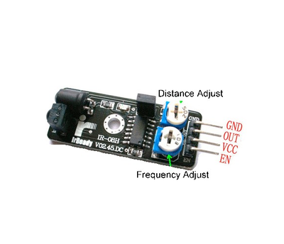
- IR-O8H: A compact sensor module for simple obstacle detection. It operates at low voltage and has a straightforward digital output.
- KY-033: An adjustable IR sensor often used in robotics. It has a longer detection range and adjustable sensitivity.
- Sharp GP2Y0A21YK0F: A popular sensor for distance measurement, offering an analog output that varies with distance.
- TCRT5000: A reflective sensor used in line-following robots. It emits IR light and detects reflections for close-range detection.
Overview of Common IR Sensors for Obstacle Detection #
| Sensor Model | Characteristics | Ideal Use Case | Price |
|---|---|---|---|
| Basic obstacle detection; low voltage; digital output | Simple obstacle detection | ||
| Adjustable sensitivity; medium-range detection; digital output | Robotics and longer-range detection | ||
| Precise distance measurement; analog output | Accurate distance sensing | ||
| Close-range reflective sensor; digital output | Line-following robots |
Advantages and Limitations of IR-Based Detection #
Advantages:
- Cost-Effective: IR sensors are affordable and widely available.
- Simple to Interface: IR sensors are easy to use with microcontrollers.
- Reliable for Short-Range Detection: Effective for detecting obstacles in low-light conditions.
Limitations:
- Sensitivity to Ambient Light: Bright sunlight or other strong IR sources can interfere with sensor accuracy.
- Surface Reflection Dependency: Highly reflective or transparent surfaces may affect the detection range and reliability.
IR Sensors Principle of Operation #
IR sensors detect obstacles by emitting infrared light and measuring the reflection. When an object is within range, the sensor detects the reflected infrared light, signaling the presence of an obstacle. This simple principle makes IR sensors popular for proximity sensing and basic distance measurement.
Types of IR Sensor Outputs #
- Digital Output: Provides a binary signal (HIGH/LOW) when an object is detected. Sensors like the IR-O8H use this output type.
- Analog Output: Provides a continuous voltage level based on the distance to the object. Sensors like the Sharp GP2Y0A21YK0F use an analog output, making them suitable for precise distance measurement.
Setting Up the Hardware with ESP32 #
For this tutorial, we’ll focus on using the IR-O8H module, which has a digital output signal.
Required Components #
- ESP32 development board
- IR-O8H module
- Jumper wires
- Breadboard (optional)
Circuit Diagram and Wiring for IR-O8H #
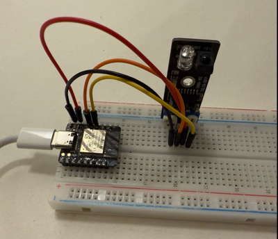
To connect the IR-O8H to the ESP32, follow these steps:
- Connect the VCC pin of the IR-O8H to the 3.3V pin on the ESP32.
- Connect the GND pin of the IR-O8H to a GND pin on the ESP32.
- Connect the OUT pin of the IR-O8H to GPIO 5 on the ESP32 (or any other GPIO pin).
Wiring Diagram #
ESP32           IR-O8H
------          ------
3.3V    <---->  VCC
GND     <---->  GND
GPIO 5  <---->  OUT
Programming the ESP32 for Obstacle Detection #
Setting Up in the Arduino IDE #
- Install ESP32 Board Support: Open the Arduino IDE and navigate to File > Preferences. Add the following URL to the Additional Board Manager URLs field:
https://dl.espressif.com/dl/package_esp32_index.json
- Install the ESP32 Board: Go to Tools > Board > Board Manager, search for "ESP32," and install the ESP32 package.
- Select Your ESP32 Board: Go to Tools > Board and select your specific ESP32 model.
Code for Digital IR Sensors (e.g., IR-O8H) #
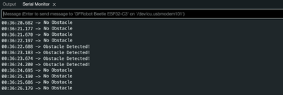
The following code reads a digital signal from the IR-O8H sensor. When an object is detected within range, it outputs "Obstacle Detected" to the Serial Monitor.
#define IR_SENSOR_PIN 5  // Define the GPIO pin connected to the IR sensor

void setup() {
Serial.begin(115200);         // Initialize Serial Monitor for debugging
pinMode(IR_SENSOR_PIN, INPUT); // Set the IR sensor pin as input
}

void loop() {
int sensorState = digitalRead(IR_SENSOR_PIN);  // Read the sensor's digital output

if (sensorState == LOW) {      // LOW indicates an obstacle is detected
 Serial.println("Obstacle Detected!");
} else {
 Serial.println("No Obstacle");
}

delay(500); // Delay for readability in the Serial Monitor
}
Code Breakdown #
- Define the Pin:
IR_SENSOR_PINis assigned to the GPIO pin connected to the IR sensor's output (e.g., GPIO 5 in our example). - Initialize Serial Monitor:
Serial.begin(115200);starts communication with the Serial Monitor at a baud rate of 115200, allowing us to view real-time output for debugging. - Reading the Sensor:
digitalRead(IR_SENSOR_PIN);reads the digital signal from the sensor. With the IR-O8H sensor,LOWusually indicates an obstacle is detected, whileHIGHmeans no obstacle is in range. - Conditional Check: The code checks
sensorState. If the state isLOW, it prints "Obstacle Detected!" If it’sHIGH, it prints "No Obstacle". - Delay:
delay(500);adds a half-second pause in the loop for readability in the Serial Monitor.
Testing and Calibrating the Sensors #
After uploading the code to the ESP32, open the Serial Monitor to observe output from the IR sensor in real-time. Follow these steps for testing:
- Place an Object in Front of the Sensor: Hold an object at different distances from the IR sensor.
- Observe the Output: The Serial Monitor should display "Obstacle Detected!" when an object is within range and "No Obstacle" when the area is clear.
- Vary the Distance: Move the object closer and farther to see how the sensor responds.
Calibrating the Sensor (If Applicable) #
Some IR sensors, like the KY-033, have a potentiometer to adjust sensitivity. If your sensor has this feature, you can fine-tune its sensitivity by following these steps:
- Adjust the Potentiometer: Use a small screwdriver to turn the potentiometer clockwise to increase range or counterclockwise to decrease it.
- Test at Different Distances: Place an object at your desired detection distance, adjusting the potentiometer until the sensor reliably detects or ignores the object at that range.
- Reduce Interference: Avoid ambient light sources that could affect sensor readings, as IR sensors are sensitive to IR from other sources, like sunlight or fluorescent lighting.
Tips for Improving Accuracy:
- Shield the Sensor: Use a small enclosure to protect the sensor from ambient light interference.
- Surface Testing: Some surfaces reflect IR better than others. Test different surfaces to ensure reliable detection.
7. Conclusion #
In this guide, we explored using an ESP32 with IR sensors for obstacle detection and distance measurement. We covered:
- The importance of obstacle detection in robotics, automation, and IoT.
- Different types of IR sensors, their characteristics, and applications.
- Setting up an IR sensor (IR-O8H) with the ESP32.
- Writing and testing code to detect obstacles.
This project provides a foundation for experimenting with other IR sensors, such as analog-output sensors for distance measurement or reflective sensors for line-following robots. Feel free to expand this project to suit various IoT and robotic applications, adding features like multiple sensors or integrating additional functions with the ESP32.


