
How to Use ESP32-S3 SuperMini with SSD1306 OLED and Button
Learn how to wire and program the ESP32-S3 SuperMini with an SSD1306 OLED display and a pushbutton. Display text, detect input, and set the stage for interactive projects or games.
Tiny board, tiny screen-tons of possibilities. The ESP32-S3 SuperMini is a super compact dev board based on the powerful ESP32-S3 chip, and when you pair it with a little SSD1306 OLED screen, things get fun fast.
The SSD1306 OLED is a 128×64 monochrome display that’s ridiculously easy to use over I2C. It’s sharp enough for clean text, simple icons, and even small animations. And since it draws very little power, it's perfect for battery-powered gadgets.
In this post, we’ll walk through:
- 🧩 Wiring the ESP32-S3 SuperMini to the OLED display
- 🧪 Setting up the display using the Adafruit SSD1306 library
- ✍️ Showing text and graphics on screen
- 🔘 Hooking up a button and making it interactive
By the end, you’ll have a working mini interface that reacts to button presses-perfect groundwork for building menus, games, or cool animated displays.
Parts Required #
You only need a handful of components to follow along with this project:
- ESP32 Board

ESP32-S3 Super Mini Development Board
- SSD1306 OLED Display (128x64, I2C)

SSD1306 OLED Module
- Tactile Pushbutton

12x12mm Pushbuttons
- Breadboard and Jumper Wires (optional but helpful)

Breadboard and Jumper Wires
💡 Tip: Some SSD1306 displays are 3.3V-only, others work with 5V. The ESP32-S3 SuperMini provides both via its USB power and onboard regulator, so you're covered either way.
Wiring the OLED Display #
We’re using the SSD1306 in I2C mode, which keeps things simple-just two data pins, plus power and ground. Here's how to hook it up to the ESP32-S3 SuperMini:
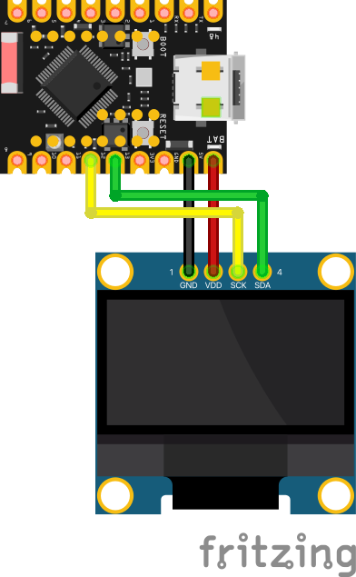
| ESP32-S3 GPIO | SSD1306 |
|---|---|
| 5V | VDD |
| GND | GND |
| 12 | SDA |
| 11 | SCL |
🛠️ You can choose different GPIOs for SDA and SCL if needed-just make sure to update the code accordingly with
Wire.begin(SDA, SCL). The ESP32-S3 allows almost any GPIO to be used for I2C, so feel free to adjust based on your board layout or available pins.
Once everything is wired up, you’re ready to move on to initializing the display and sending your first message to the screen.
Basic Display Setup with Adafruit Library #
To get the SSD1306 up and running, we’ll use the popular Adafruit_SSD1306 and Adafruit_GFX libraries. These libraries make it easy to draw text, shapes, and bitmaps on the OLED.
First, install both libraries via the Arduino Library Manager:
- Open the Arduino IDE
- Go to Tools → Manage Libraries
- Search for
Adafruit SSD1306and install it - Search for
Adafruit GFXand install that too
Example Code #
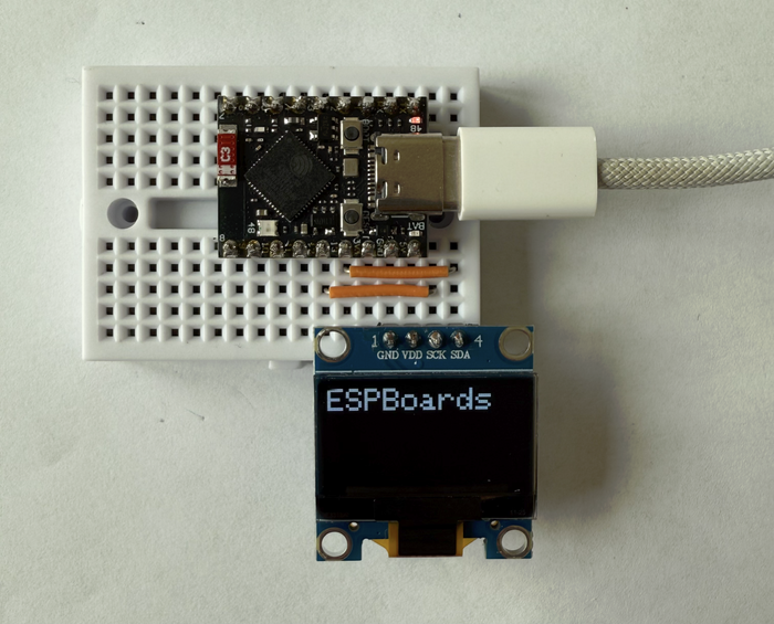
Here’s a minimal sketch that sets up the display using custom I2C pins and prints "ESPBoards" in a big font:
#include <Wire.h>
#include <Adafruit_GFX.h>
#include <Adafruit_SSD1306.h>

#define I2C_SDA 12
#define I2C_SCL 11

#define SCREEN_WIDTH 128 // OLED width,  in pixels
#define SCREEN_HEIGHT 64 // OLED height, in pixels

Adafruit_SSD1306 oled(SCREEN_WIDTH, SCREEN_HEIGHT, &Wire, -1);

void setup() {
  Serial.begin(9600);

  // Setup I2C on custom pins
  Wire.begin(I2C_SDA, I2C_SCL);

  // Initialize OLED display with I2C address 0x3C
  if (!oled.begin(SSD1306_SWITCHCAPVCC, 0x3C)) {
    Serial.println(F("failed to start SSD1306 OLED"));
    while (1);
  }
  Serial.println("OLED Init success");

  delay(2000);         // wait two seconds for initializing
  oled.clearDisplay(); // clear display

  oled.setTextSize(2);         // set text size
  oled.setTextColor(WHITE);    // set text color
  oled.setCursor(0, 2);       // set position to display (x,y)
  oled.println("ESPBoards"); // set text
  oled.display();              // display on OLED
}

void loop() {
}
When uploaded, you should see “ESPBoards” pop up on the OLED in large text. If the screen stays blank, double-check the wiring, I2C address (0x3C is common), and that the board is receiving 5V power.
You’re now displaying text - next up, let’s make it interactive.
Adding a Button for Interaction #
Now let’s make things interactive. A single button adds a lot of potential-menus, inputs, games, or just giving your project a bit of personality.
We'll wire up a pushbutton to GPIO11 and use the ESP32’s built-in pull-up resistor to keep things minimal-no external components needed.
Wiring the Button #
Here’s the updated wiring layout with the button added:
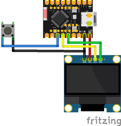
| ESP32-S3 GPIO | SSD1306 | Button |
|---|---|---|
| 5V | VDD | - |
| GND | GND | GND |
| 13 | SDA | - |
| 12 | SCL | - |
| 11 | - | YES |
We're now using GPIO13 for SDA and GPIO12 for SCL, leaving GPIO11 free for the button. You can pick other pins, but make sure they don't conflict with other functions (like USB or flash).
Code: Button-Driven Counter Display #
#include <Wire.h>
#include <Adafruit_GFX.h>
#include <Adafruit_SSD1306.h>

#define I2C_SDA 13
#define I2C_SCL 12
#define BUTTON_PIN 11

#define SCREEN_WIDTH 128 // OLED width,  in pixels
#define SCREEN_HEIGHT 64 // OLED height, in pixels

Adafruit_SSD1306 oled(SCREEN_WIDTH, SCREEN_HEIGHT, &Wire, -1);

int counter = 0;
bool lastButtonState = HIGH; // Button unpressed state due to INPUT_PULLUP

void setup() {
  Serial.begin(9600);

  pinMode(BUTTON_PIN, INPUT_PULLUP); // Button with pull-up resistor

  // Setup I2C on custom pins
  Wire.begin(I2C_SDA, I2C_SCL);

  // Initialize OLED display with I2C address 0x3C
  if (!oled.begin(SSD1306_SWITCHCAPVCC, 0x3C)) {
    Serial.println(F("failed to start SSD1306 OLED"));
    while (1);
  }
  Serial.println("OLED Init success");

  oled.clearDisplay();
  oled.setTextSize(2);
  oled.setTextColor(WHITE);
  oled.setCursor(0, 0);
  oled.println("ESPBoards");

  oled.setTextSize(1);
  oled.setCursor(0, 40);
  oled.print("Counter: ");
  oled.println(counter);
  oled.display();
}

void loop() {
  bool buttonState = digitalRead(BUTTON_PIN);

  if (buttonState == LOW && lastButtonState == HIGH) { // Detect button press
    counter++;
    Serial.println(counter);

    oled.clearDisplay();
    oled.setTextSize(2);
    oled.setCursor(0, 0);
    oled.println("ESPBoards");

    oled.setTextSize(1);
    oled.setCursor(0, 40);
    oled.print("Counter: ");
    oled.println(counter);
    oled.display();

    delay(200); // Simple debounce delay
  }

  lastButtonState = buttonState;
}
Now every time you press the button, the counter increases, and the display updates in real time. Super simple, but a great building block for games, interactive menus, or status displays.
🛠️ Troubleshooting #
If your OLED display stays blank or something's not working right, here are a few common issues and how to fix them:
🔌 Double-check wiring
Make sure SDA and SCL are connected to the correct GPIO pins on the ESP32-S3, and that you've updatedWire.begin(SDA, SCL)in your code to match.⚡ Verify OLED power
Some SSD1306 displays are 3.3V only, others are fine with 5V. Check your specific module. If in doubt, try both-just avoid mixing up GND and VCC.🔍 Wrong I2C address
The default I2C address0x3Cworks for most displays, but not all. Run an I2C Scanner sketch to detect the correct address. It’s quick and super helpful!🧠 Display not initializing
Ifoled.begin()fails, confirm:- Your wiring is solid
- The display is in I2C mode (check jumpers/solder pads)
- Your I2C pins are free and not used by other peripherals
🕹️ Button not responding
Make sure the button connects between the GPIO and GND, and that you’re usingINPUT_PULLUPin thepinMode()setup. Still unsure? Add aSerial.println()to confirm state changes.
🔁 Pro Tip: Try breaking things down-test the screen alone with a minimal sketch, or try the button separately. Isolating each part helps pinpoint the issue quickly.
What's next #
Coming up next: we’ll use this exact setup to build a Flappy Bird-style game, complete with gravity, pixel pipes, and some good ol’ button smashing. 🐦💥
Until then, try modifying the display output, adding a second button, or even animating an icon. You've got the essentials down-time to get creative!
Wrapping Up #
You've now got your ESP32-S3 SuperMini talking to an SSD1306 OLED and responding to button presses-an awesome base for all sorts of projects. With just a handful of components, you've built a tiny UI that can display messages, respond to input, and evolve into something much cooler.
Here’s what you’ve set up:
- ✅ Custom I2C wiring with flexible pin assignment
- ✅ OLED screen showing crisp text
- ✅ Button input with live display updates
Not bad for just a few lines of code.