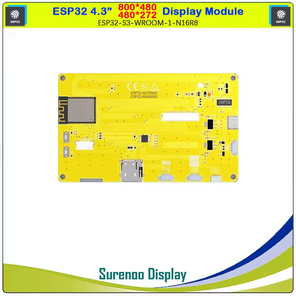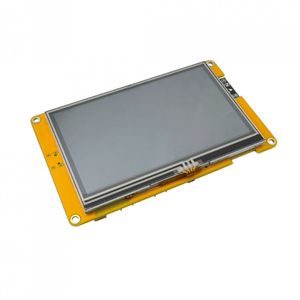
CYD ESP32-4827S043 is a development board based on the ESP32 microcontroller using XTENSA architecture.
This board features a maximum CPU frequency of 240 MHz and 32Mbit flash memory.
About CYD ESP32-4827S043
🚀 The CYD ESP32-4827S043 is a budget-friendly ESP32-based development board, commonly referred to as a Cheap Yellow Display (CYD). It features integrated WiFi, Bluetooth 4.2, and a 4.3-inch 480x272 TN LCD, making it an excellent choice for affordable IoT and embedded display projects. ⚡
📡 With support for 802.11 B/G/N WiFi and Bluetooth 4.2 (BLE), this board is well-suited for wireless applications.
💾 Equipped with 32Mbit SPI Flash, multiple ADC, DAC, I2C, SPI, UART, PWM, and I2S interfaces, it offers a versatile platform for various embedded projects.
Where to Buy CYD ESP32-4827S043
Prices are subject to change. We earn from qualifying purchases as an Amazon Associate.
CYD ESP32-4827S043 Technical Specifications
🖥️ Display
🛰️ Connectivity
🧠 Microcontroller
✨ Features
- 21 digital IO pins
- 22 external interrupt pins
- 6 analog input pins
- 14 PWM pins
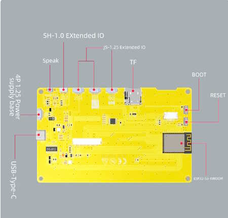
CYD ESP32-4827S043 Pinout
Safe Pins to Use
For general GPIO usage, these are the safest and most flexible choices:
Why Are These Pins Safe?
- • Not involved in bootstrapping → No impact on device boot mode or system startup
- • Not linked to flash memory or PSRAM → Won't interfere with storage or memory access
- • Not dedicated to USB or JTAG → Free for general use without affecting debugging
- • No special hardware connections → Freely assignable without internal conflicts
Pins to Avoid or Use with Caution
Critical Pin Categories:
- Strapping Pins: Control boot behavior and flash voltage selection
- JTAG Debugging Pins: Required for low-level debugging
- USB Communication Pins: Used for USB Serial/JTAG communication
- Flash Memory & SPI Pins: Connected to SPI flash memory and PSRAM
- UART Serial Communication Pins: Used for debugging and firmware uploads
| PIN | Label | Reason | Function |
|---|---|---|---|
| IO1 | U0TXD (GPIO1) | Connected to on-board USB-UART for uploading and logs; drives serial output at boot, so using as GPIO can disrupt programming or console. | 🔌 USB |
| IO2 | GPIO2 | If driven HIGH on reset (while IO0 is LOW), selects an unsupported SDIO boot mode, causing boot failure. | 🛠️ Strapping |
| IO3 | U0RXD (GPIO3) | Used for receiving data from USB-UART (programming); also pulled HIGH at boot for console communication, so using as GPIO can disrupt uploads. | 🔌 USB |
| IO16 | GPIO16 | Connected to internal PSRAM on PSRAM-enabled modules; not usable as GPIO on those modules. | ⚡ Flash |
| IO17 | GPIO17 | Connected to internal PSRAM on PSRAM-enabled modules; not usable as GPIO on those modules. | ⚡ Flash |
CYD ESP32-4827S043 Custom Pins
This development board provides 21 digital IO pins, out of which 22 can be used as external interrupt pins , 6 as analog input pins and 14 pins have Pulse-Width Modulation (PWM).
| Pin | Function | ESP Pin | Input/Output | Description |
|---|---|---|---|---|
| 1 | 3V3 | 3.3V | POWER OUTPUT | 3.3V power output |
| 2 | GND | GND | POWER GROUND | Ground connection |
| 3 | 5V | 5V | POWER INPUT | 5V power input |
| 4 | IO1 | GPIO1 | BIDIRECTIONAL | GPIO, ADC, I2C |
| 5 | IO2 | GPIO2 | BIDIRECTIONAL | GPIO, ADC |
| 6 | IO3 | GPIO3 | BIDIRECTIONAL | GPIO, ADC |
| 7 | IO16 | SPI_CS | BIDIRECTIONAL | GPIO, SPI Chip Select |
| 8 | IO17 | SPI_D | BIDIRECTIONAL | GPIO, SPI Data |
| 9 | IO18 | SPI_CLK | BIDIRECTIONAL | GPIO, SPI Clock |
| 10 | IO19 | SPI_Q | BIDIRECTIONAL | GPIO, SPI Q |
| 11 | IO21 | UART_TX | OUTPUT | GPIO, UART TX |
| 12 | IO22 | UART_RX | INPUT | GPIO, UART RX |
Default Tools for CYD ESP32-4827S043
| Bootloader tool | esptool_py |
| Uploader tool | esptool_py |
| Network uploader tool | esp_ota |
| Bootloader address | 0x1000 |
| Flash mode | dio |
| Boot mode | qio |
| Maximum upload size | 1280 Kb (1310720 B) |
| Maximum data size | 320 Kb (327680 B) |
The CYD ESP32-4827S043 development board by default uses esptool_py uploader tool, network uploader tool for Over-the-air (OTA) uploads and esptool_py bootloader tool. The bootloader starts at address "0x1000". Flash mode and boot mode for CYD ESP32-4827S043 development board by default is dio and qio respectively.
