
Espressif ESP32-LyraTD-DSPG
Audio dev board with DSP Group tech for voice interfaces - suitable for wake-word detection and AI audio input.

Espressif ESP32-LyraTD-DSPG Pinout
23 pins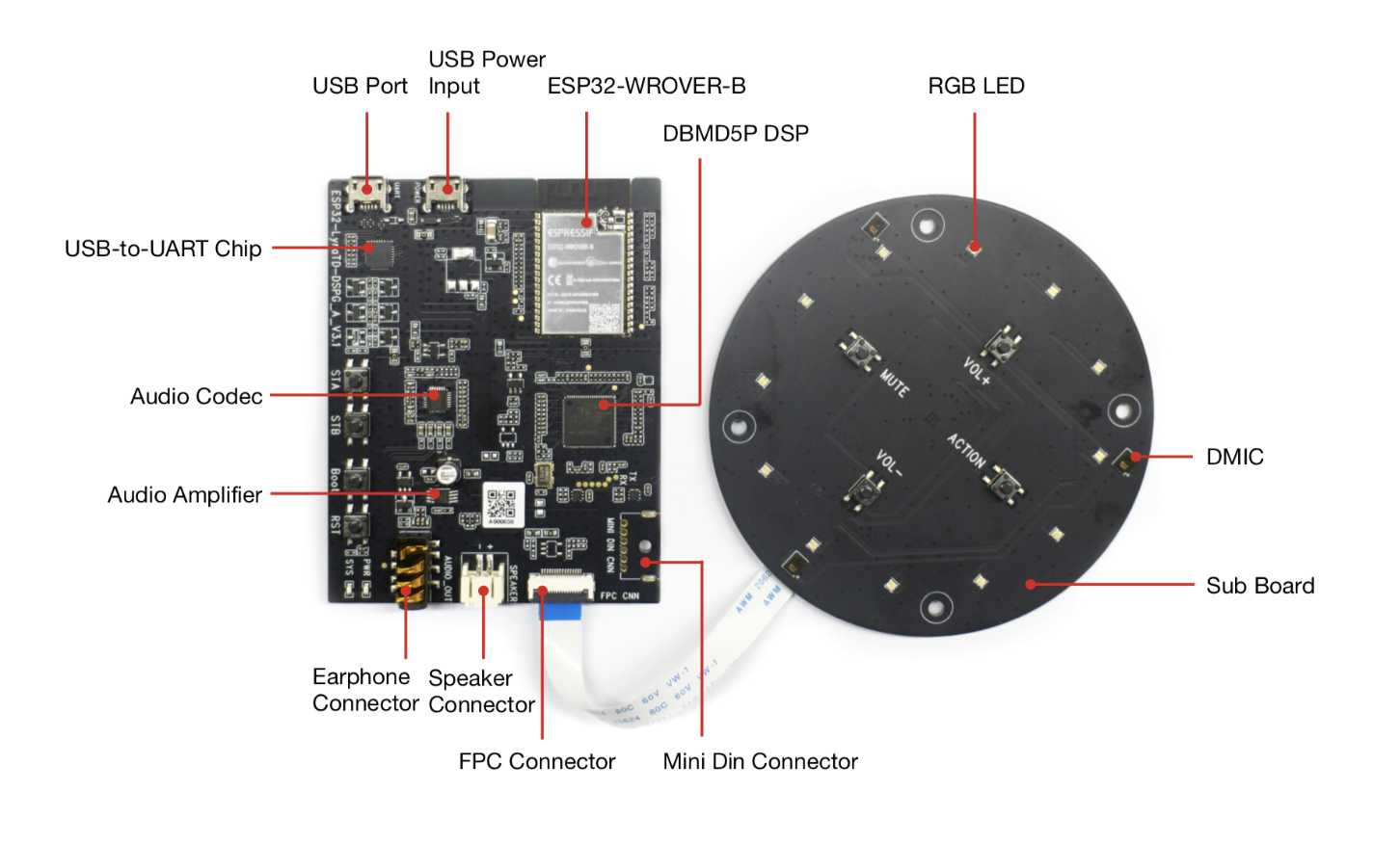
| Pin | GPIO | Labels | Status | Capabilities | Notes |
|---|---|---|---|---|---|
| 1 | 0 | IO0Boot_IO0ES_I2S_MCLK | strapping | adc · touch | Strapping/boot pin. ES8388 I2S master clock (ES_I2S_MCLK) and auto-program IO0 (Boot_IO0); the net GPIO0_DSP_MASTER_CLK to the DSP also lands here through an unpopulated 0R option (R10) |
| 2 | 1 | TXD0IO1U0TXD | uart | uart | UART0 TX to the CP2102N USB-UART bridge (console and programming) |
| 3 | 2 | IO2DSP_APR_WAKEUP_3V3 | strapping | adc · touch | Strapping pin. DBMD5P APR wake-up line (DSP_APR_WAKEUP_3V3); the Boot_IO2 auto-program option (R29) is not populated |
| 4 | 3 | RXD0IO3U0RXD | uart | uart | UART0 RX from the CP2102N USB-UART bridge (console and programming) |
| 5 | 4 | IO4DSP_VT_RSTN_3V3 | safe | adc · touch | DBMD5P voice-trigger (VT) core reset (DSP_VT_RSTN_3V3) |
| 6 | 5 | IO5ES_I2S_SCLK | strapping | - | Strapping pin. ES8388 I2S bit clock (ES_I2S_SCLK); a DSP_APR_I2S_BCLK_3V3 option (R13) shares this GPIO |
| 7 | 12 | IO12MTDISystem_LED | strapping | adc · touch | Strapping pin (flash voltage). Drives the System LED on the sub board (System_LED, high = on); JTAG test point TP1 (TDI) |
| 8 | 13 | IO13MTCKDSP_APR_SPI_CLK | strapping | adc · touch | DBMD5P APR SPI clock (DSP_APR_SPI_CLK); JTAG test point TP2 (TCK) |
| 9 | 14 | IO14MTMSDSP_VT_WAKEUP_3V3 | strapping | adc · touch | DBMD5P voice-trigger wake-up line (DSP_VT_WAKEUP_3V3); JTAG test point TP3 (TMS) |
| 10 | 15 | IO15MTDODSP_VT_I2S_LevShift_EN_L | strapping | adc · touch | Strapping pin. Enable (active low) for the DSP voice-trigger I2S level shifter (DSP_VT_I2S_LevShift_EN_L); JTAG test point TP4 (TDO) |
| 11 | 18 | SDAIO18IO18_I2C_SDA | safe | - | Shared I2C SDA - ES8388 codec control and the sub board LED driver (via the FPC link) |
| 12 | 19 | IO19DSP_APR_SPI_MOSI | safe | - | DBMD5P APR SPI MOSI (DSP_APR_SPI_MOSI) |
| 13 | 21 | IO21DSP_APR_RSTN_3V3 | safe | - | DBMD5P APR core reset (DSP_APR_RSTN_3V3) |
| 14 | 22 | IO22PA_CTRL | safe | - | Power amplifier enable (PA_CTRL); gated off by the earphone-detect logic when a plug is inserted |
| 15 | 23 | SCLIO23IO23_I2C_SCL | safe | - | Shared I2C SCL - ES8388 codec control and the sub board LED driver (via the FPC link) |
| 16 | 25 | IO25ES_I2S_LRCKDAC1 | safe | adc · dac | ES8388 I2S word/LR clock (ES_I2S_LRCK); a DSP_APR_I2S_LRCK_3V3 option (R15) shares this GPIO |
| 17 | 26 | IO26ES_I2S_DSDINDAC2 | safe | adc · dac | ES8388 I2S data from ESP32 to codec (ES_I2S_DSDIN); a DSP_APR_I2S_DO_3V3 option (R17) shares this GPIO |
| 18 | 27 | IO27DSP_APR_SPI_MISO | safe | adc · touch | DBMD5P APR SPI MISO (DSP_APR_SPI_MISO) |
| 19 | 32 | IO32DSP_APR_SPI_CS | safe | adc · touch | DBMD5P APR SPI chip select (DSP_APR_SPI_CS) |
| 20 | 33 | IO33DSP_VT_SPI_SCS_3V3 | safe | adc · touch | DBMD5P voice-trigger SPI chip select (DSP_VT_SPI_SCS_3V3) |
| 21 | 35 | IO35DSP_VT_I2S_DI_3V3 | strapping | adc | Input-only GPIO. I2S data in from the DBMD5P voice-trigger output (DSP_VT_I2S_DI_3V3) |
| 22 | 36 | SENSOR_VPIO36DBMD_INT_3V3 | strapping | adc | Input-only GPIO. DBMD5P interrupt line (DBMD_INT_3V3) |
| 23 | 39 | SENSOR_VNIO39Button_Array_ADC | strapping | adc | Input-only GPIO. Sub board key ladder (Button_Array_ADC), Vol+, Mute, Vol-, Action read as different voltages |
Start with these
11 pins with no boot or system involvementFreely assignable - no strapping, flash, USB or JTAG duties. Ideal first picks for buttons, sensors and LEDs.
Fine - with a little care
12 pins · 11 things to knowIO0 Bootstrapping pin (enter bootloader when low); internal pull-up. Strapping
Must be HIGH during boot for normal startup; if held LOW on reset, forces flash programming mode.
TXD0GPIO1 Default UART0 TX pin for USB-serial programming and console. UART
Connected to on-board USB-UART for uploading and logs; drives serial output at boot, so using as GPIO can disrupt programming or console.
IO2 Bootstrapping pin; internal pull-down. Any level boots normally from flash, but it must be LOW or floating (with GPIO0 LOW) to enter download mode. Strapping
If held HIGH at reset, the chip cannot enter download mode, so flashing fails.
RXD0GPIO3 Default UART0 RX pin for USB-serial programming (console input). UART
Used for receiving data from USB-UART (programming); also pulled HIGH at boot for console communication, so using as GPIO can disrupt uploads.
IO5 Bootstrapping pin; internal pull-up; VSPI CS0 (default SPI chip-select); acts as FSPIWP (flash write-protect) on internal-flash variants. Strapping
Sampled at reset (internal pull-up) with MTDO to set the SDIO slave timing; this only matters when the ESP32 runs as an SDIO slave.
IO12 Bootstrapping pin; JTAG TDI; sets flash voltage (VDD_SDIO); also HSPIQ (flash data line). Strapping
Keep LOW during boot (internal PD); pulling HIGH at reset selects 1.8V flash, and a module with 3.3V flash then fails to boot. espefuse set-flash-voltage 3.3V makes its level irrelevant.
IO13 JTAG clock pin (TCK); also ADC2 channel 4 / Touch4 input. JTAG
Used for JTAG debugging (TCK); avoid using as GPIO if JTAG is needed.
IO14 JTAG mode select pin (TMS); also HSPI CLK and PWM-capable GPIO. JTAG
Used for JTAG debugging (TMS); driving it as GPIO may interfere with JTAG or produce spurious signals at boot.
IO15 Bootstrapping pin; JTAG TDO; controls UART0 boot log output; also HSPICS0 (secondary SPI CS). Strapping
Keep HIGH during boot (internal PU); if LOW at reset, the ROM boot log on U0TXD is silenced and the SDIO slave timing changes.
IO35SENSOR_VNGPIO39 Input-only GPIOs with ADC1 channels - no output driver Other
Cannot be used as output; only suitable for input.
- IO35Input-only GPIO (no output driver); ADC1 channel 7.
- SENSOR_VNInput-only GPIO (no output); ADC1 channel 3, Hall sensor VN.
SENSOR_VPGPIO36 Input-only GPIO (no output); ADC1 channel 0, Hall sensor VP. Other
Cannot be used as output; only suitable for input (e.g., analog read).
All 23 pins on the Espressif ESP32-LyraTD-DSPG are usable GPIO.
Peripheral wiring is straightforward: I²C is mapped to SDA on GPIO18 and SCL on GPIO23.
Beyond plain digital I/O you get 15 ADC-capable pins for sensors and battery monitoring, 10 capacitive-touch inputs and 2 true DAC outputs.
12 of the exposed pins carry boot-time or system duties on the ESP32 (IO0, TXD0, IO2 and 9 more) - check the guidance above before wiring anything to them. IO4, SDA, IO19, IO21 and 7 more are free of any such role - the safest first picks.
Getting started
flash your first firmware in ~2 minutesBoard: ESP32 Wrover Module Flash Size: 16MB (128Mb) Flash Mode: DIO PSRAM: QSPI PSRAM Partition Scheme: 16M Flash (3MB APP/9.9MB FATFS) Upload Speed: 921600
// toggle GPIO4 - wire an LED and resistor to it
void setup() {
  pinMode(4, OUTPUT);
}
void loop() {
  digitalWrite(4, HIGH); delay(500);
  digitalWrite(4, LOW);  delay(500);
}[env:esp32-lyratd-dspg]
platform = espressif32
board = esp32dev
framework = arduino
monitor_speed = 115200
upload_speed = 921600
board_build.arduino.memory_type = qio_qspi
build_flags = -DBOARD_HAS_PSRAMesp32dev - or type it after board =.esp32:
board: esp32dev
variant: esp32
framework:
type: esp-idf
psram:
mode: quad
speed: 80MHz
# blink - GPIO4
output:
- platform: gpio
pin: 4
id: led_out
light:
- platform: binary
name: "LED"
output: led_outesp32dev (same ids as PlatformIO).esptool.py --chip esp32 --port /dev/ttyACM0 \
--baud 921600 write_flash 0x1000 firmware.bin--port = your /dev/tty* (macOS/Linux) or COMx (Windows).Specifications
ESP32 · vs other ESP32 chips →About this board
Inside sits the ESP32 - a dual-core Xtensa with both Bluetooth Classic and BLE.
At $30.00 it's on the expensive side for an ESP32 board - most land around $20.
Around the module: 8MB (QSPI) PSRAM, a microphone (3-mic array), a speaker connector, an audio codec (ES8388), an amplifier and EN/Action/Vol+/Vol-/Mute buttons.
The ESP32-LyraTD-DSPG is an advanced voice development board featuring the ESP32-WROVER module. It integrates DSP Group's DBMD5P digital signal processor for high-performance voice processing, making it ideal for far-field voice recognition applications such as smart speakers and AI-powered voice assistants. The board supports Wi-Fi and Bluetooth connectivity, an onboard audio codec, microphone array, and multiple peripheral interfaces for seamless integration.
- DBMD5P dual-core programmable voice DSP (DSP Group) for wake-word detection and acoustic echo cancellation
- Three-microphone (DMIC) far-field array on a detachable sub board
- RGB LED ring (Echo Dot-style) driven by an onboard LED driver
- 3.5mm earphone/headphone jack with audio routed through the ES8388 codec
- Two-board design - main board plus sub board linked by an FPC ribbon cable
- Optional Mini DIN connector for an external microphone cable (not mounted by default)
- Cloud voice support - Amazon AVS, Google Dialogflow and Google Voice Assistant
Where to buy
prices are typical street pricesResources
Similar boards


