
LilyGo TTGO T-Display 1.14 Inch LCD ESP32
ESP32 dev board with built-in 1.14" color display - perfect for dashboards, wearables, and visual IoT interfaces.

LilyGo TTGO T-Display 1.14 Inch LCD ESP32 Pinout
24 pins · 2.54 mm pitch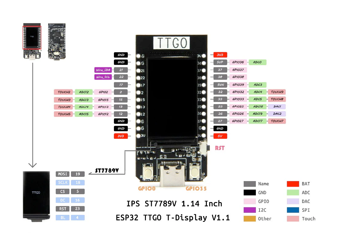
| Pin | GPIO | Labels | Status | Capabilities | Notes |
|---|---|---|---|---|---|
| 1 | - | GND | ground | - | Left header; ground |
| 2 | - | GND | ground | - | Left header; ground |
| 3 | 21 | GPIO21SDA | safe | pwm · i2c | Left header; default I2C SDA (10k pull-up fitted on board) |
| 4 | 22 | GPIO22SCL | safe | pwm · i2c | Left header; default I2C SCL (10k pull-up fitted on board) |
| 5 | 17 | GPIO17 | safe | pwm | Left header; free GPIO (UART2 TX capable) |
| 6 | 2 | GPIO2T2 | strapping | adc · touch · pwm | Left header; strapping pin, ADC2_CH2 / Touch2 |
| 7 | 15 | GPIO15T3 | strapping | adc · touch · pwm | Left header; strapping pin, ADC2_CH3 / Touch3 |
| 8 | 13 | GPIO13T4 | strapping | adc · touch · pwm | Left header; ADC2_CH4 / Touch4 |
| 9 | 12 | GPIO12T5 | strapping | adc · touch · pwm | Left header; strapping pin (hold low at boot), ADC2_CH5 / Touch5 |
| 10 | - | GND | ground | - | Left header; ground |
| 11 | - | GND | ground | - | Left header; ground |
| 12 | - | 3V33.3V | power | - | Left header; 3.3V output |
| 13 | - | 3V33.3V | power | - | Right header; 3.3V output |
| 14 | 36 | GPIO36SVP | strapping | adc | Right header; input-only, ADC1_CH0 (SENSOR_VP); 270pF cap to GPIO37 |
| 15 | 37 | GPIO37 | strapping | adc | Right header; input-only, ADC1_CH1; 270pF cap to GPIO36 |
| 16 | 38 | GPIO38 | strapping | adc | Right header; input-only, ADC1_CH2; 270pF cap to GPIO39 |
| 17 | 39 | GPIO39SVN | strapping | adc | Right header; input-only, ADC1_CH3 (SENSOR_VN); 270pF cap to GPIO38 |
| 18 | 32 | GPIO32T9 | safe | adc · touch · pwm | Right header; ADC1_CH4 / Touch9 |
| 19 | 33 | GPIO33T8 | safe | adc · touch · pwm | Right header; ADC1_CH5 / Touch8 |
| 20 | 25 | GPIO25DAC1 | safe | adc · pwm · dac | Right header; DAC1 / ADC2_CH8 |
| 21 | 26 | GPIO26DAC2 | safe | adc · pwm · dac | Right header; DAC2 / ADC2_CH9 |
| 22 | 27 | GPIO27T7 | safe | adc · touch · pwm | Right header; ADC2_CH7 / Touch7 |
| 23 | - | GND | ground | - | Right header; ground |
| 24 | - | 5VVIN | power | - | Right header; 5V from USB / VIN |
Start with these
8 pins with no boot or system involvementFreely assignable - no strapping, flash, USB or JTAG duties. Ideal first picks for buttons, sensors and LEDs.
Fine - with a little care
8 pins · 6 things to knowGPIO2 Bootstrapping pin (must be low or floating at reset); internal pull-down. Strapping
If driven HIGH on reset (while IO0 is LOW), selects an unsupported SDIO boot mode, causing boot failure.
GPIO15 Bootstrapping pin; JTAG TDO; controls UART0 boot log output; also HSPICS0 (secondary SPI CS). Strapping
Keep HIGH during boot (internal PU); if LOW on reset, bootloader log is silenced and boot mode may change.
GPIO13 JTAG clock pin (TCK); also ADC2 channel 4 / Touch4 input. JTAG
Used for JTAG debugging (TCK); avoid using as GPIO if JTAG is needed.
GPIO12 Bootstrapping pin; JTAG TDI; sets flash voltage (VDD_SDIO); also HSPIQ (flash data line). Strapping
Keep LOW during boot (internal PD); pulling HIGH at reset selects 1.8V flash mode, causing flash brownout if 3.3V flash is used.
GPIO36 Input-only GPIO (no output); ADC1 channel 0, Hall sensor VP. Other
Cannot be used as output; only suitable for input (e.g., analog read).
GPIO37GPIO38GPIO39 Input-only GPIOs with ADC1 channels - no output driver Other
Cannot be used as output; only suitable for input.
- GPIO37Input-only GPIO (no output); ADC1 channel 1.
- GPIO38Input-only GPIO (no output); ADC1 channel 2.
- GPIO39Input-only GPIO (no output); ADC1 channel 3, Hall sensor VN.
The LilyGo TTGO T-Display 1.14 Inch LCD ESP32 pinout brings out 24 pins at a 2.54 mm pitch - 16 usable GPIO alongside the GND, 3V3 and 5V power rails.
Peripheral wiring is straightforward: I²C is mapped to SDA on GPIO21 and SCL on GPIO22.
Beyond plain digital I/O you get 13 ADC-capable pins for sensors and battery monitoring, PWM on 12 pins, 7 capacitive-touch inputs and 2 true DAC outputs.
8 of the exposed pins carry boot-time or system duties on the ESP32 (GPIO2, GPIO15, GPIO13 and 5 more) - check the guidance above before wiring anything to them. GPIO21, GPIO22, GPIO17, GPIO32 and 4 more are free of any such role - the safest first picks.
Getting started
flash your first firmware in ~2 minutesBoard: ESP32 Dev Module Flash Size: 4MB (32Mb) Flash Mode: QIO Partition Scheme: Default 4MB with spiffs (1.2MB APP/1.5MB SPIFFS) Upload Speed: 921600
// toggle GPIO21 - wire an LED and resistor to it
void setup() {
  pinMode(21, OUTPUT);
}
void loop() {
  digitalWrite(21, HIGH); delay(500);
  digitalWrite(21, LOW);  delay(500);
}[env:lilygo_ttgo_t_display_1_14]
platform = espressif32
board = esp32dev
framework = arduino
monitor_speed = 115200
upload_speed = 921600esp32dev - or type it after board =.esp32:
board: esp32dev
variant: esp32
framework:
type: esp-idf
# blink - GPIO21
output:
- platform: gpio
pin: 21
id: led_out
light:
- platform: binary
name: "LED"
output: led_outesp32dev (same ids as PlatformIO).esptool.py --chip esp32 --port /dev/ttyACM0 \
--baud 921600 write_flash 0x1000 firmware.bin--port = your /dev/tty* (macOS/Linux) or COMx (Windows).Specifications
ESP32 · 51.52 × 25.04 mm · vs other ESP32 chips →Dimensions
About this board
Inside sits the ESP32 - a dual-core Xtensa with both Bluetooth Classic and BLE.
At $15.99 it's cheaper than most ESP32 boards, which usually run around $20.
Only 16 GPIO are broken out, where most ESP32 boards manage about 24 - worth checking the pinout covers what you need.
Around the module: an LCD 1.14" 240x135 display, battery charging (TP4054) via JST 1.25 and Reset/IO0/IO35 buttons.
The LilyGo TTGO T-Display 1.14 Inch LCD ESP32 is a compact development board featuring an ESP32 microcontroller with integrated WiFi and Bluetooth capabilities. It includes a 1.14-inch LCD driven by an ST7789 controller, offering a vibrant display for graphical applications.
With support for WiFi 802.11 b/g/n and Bluetooth 4.2, this board is ideal for IoT and embedded display projects. It also includes 4MB Flash and 520KB SRAM for versatile applications.
Where to buy
prices are typical street pricesResources
Similar boards


