
UM TinyPICO is a development board based on the ESP32 microcontroller using XTENSA architecture.
This board features a maximum CPU frequency of 240 MHz and 4MB flash memory.
About UM TinyPICO
Ultra-small ESP32 board with USB-C, LiPo charging, and deep sleep - perfect for compact, low-power IoT projects.
Technical Specifications
Complete technical specification details for UM TinyPICO
Connectivity
Microcontroller
✨ Features & Pins
Quick Setup
Copy-paste configs for UM TinyPICO - auto‑generated from this board's exact hardware specs.
In Arduino IDE 2 select Tinypico from the esp32 by Espressif package. In PlatformIO use board = esp32dev. ESP32 · 240 MHz · 4MB · DIO.
In Arduino IDE 2, open Boards Manager, search "esp32" by Espressif and install it. Then go to Tools → Board and select "Tinypico" for the UM TinyPICO.
UM TinyPICO Pinout Diagram
Complete pin reference for UM TinyPICO
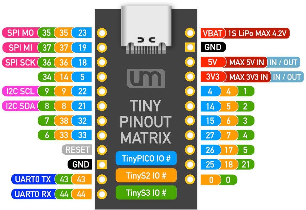
Pin Mappings
Complete pinout and GPIO mapping for UM TinyPICO
| Pin | Analog | Touch | PWM | Other |
|---|---|---|---|---|
| 0 | A11 | T1 | ||
| 1 | PWM | TX | ||
| 2 | A12 | T2 | PWM | APA_DATA |
| 3 | PWM | RX | ||
| 4 | A10 | T0 | PWM | |
| 5 | PWM | SS | ||
| 12 | A15 | T5 | PWM | APA_CLK |
| 13 | A14 | T4 | PWM | APA_POWER |
| 14 | A16 | T6 | PWM | |
| 15 | A13 | T3 | PWM | |
| 18 | PWM | SCK | ||
| 19 | PWM | MISO SDI | ||
| 21 | PWM | SDA | ||
| 22 | PWM | SCL | ||
| 23 | PWM | MOSI SDO | ||
| 25 | A18 | PWM | DAC1 | |
| 26 | A19 | PWM | DAC2 | |
| 27 | A17 | T7 | PWM | |
| 32 | A4 | T9 | PWM | |
| 33 | A5 | T8 | PWM | |
| 34 | A6 | |||
| 35 | A7 | |||
| 36 | A0 | |||
| 39 | A3 |
Default Tools & Configuration
Build and upload settings for UM TinyPICO
| Setting | Value |
|---|---|
| Bootloader tool | esptool_py |
| Uploader tool | esptool_py |
| Network uploader tool | esp_ota |
| Bootloader address | 0x1000 |
| Flash mode | dio |
| Boot mode | dio |
| Maximum upload size | 1280 KB (1310720 bytes) |
| Maximum data size | 320 KB (327680 bytes) |
The UM TinyPICO uses esptool_py for uploads , esp_ota for OTA updates, and esptool_py bootloader at 0x1000.
Flash mode: dio | Boot mode: dio
Max sketch size: 1280 KB | Max data size: 320 KB
Similar Boards
Other development boards with ESP32 microcontroller

Deneyap Kart 1A
Deneyap Kart 1A development board is based on esp32 microcontroller and uses xtensa architecture.

Denky
Denky development board is based on esp32 microcontroller and uses xtensa architecture.

Adafruit ItsyBitsy ESP32
Adafruit ItsyBitsy ESP32 development board is based on esp32 microcontroller and uses xtensa architecture.