
TTGO T1 is a development board based on the ESP32 microcontroller using XTENSA architecture.
This board features a maximum CPU frequency of 240 MHz and 4MB flash memory.
About TTGO T1
Classic ESP32 TTGO board with LiPo support and headers - great for basic wireless development and IoT builds.
Where to Buy TTGO T1

Prices are subject to change. We earn from qualifying purchases as an Amazon Associate.
Technical Specifications
Complete technical specification details for TTGO T1
Connectivity
Microcontroller
✨ Features & Pins
Quick Setup
Copy-paste configs for TTGO T1 - auto‑generated from this board's exact hardware specs.
In Arduino IDE 2 select Ttgo T1 from the esp32 by Espressif package. In PlatformIO use board = esp32dev. ESP32 · 240 MHz · 4MB · DIO.
In Arduino IDE 2, open Boards Manager, search "esp32" by Espressif and install it. Then go to Tools → Board and select "Ttgo T1" for the TTGO T1.
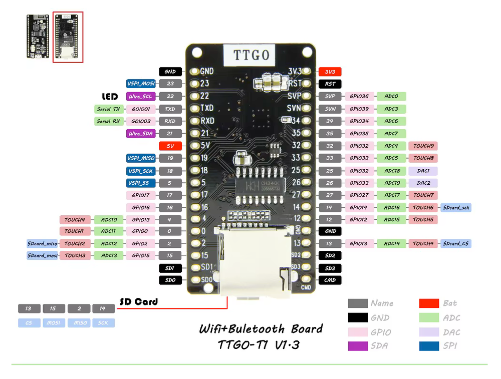
TTGO T1 Pinout Diagram
Complete pin reference for TTGO T1
Safe Pins to Use
These pins are safe for general GPIO usage without boot or system conflicts
Why Are These Pins Safe?
Pins to Avoid or Use with Caution
Reserved for critical functions. Misuse may cause boot failures, programming issues, or system conflicts.
Boot behavior & flash voltage
Low-level debugging interface
USB Serial/JTAG communication
Memory & PSRAM connections
Debugging & firmware uploads
| PIN | Label | Why Avoid | Type |
|---|
TTGO T1 Custom Pin Mapping
Pin configuration and GPIO mapping for TTGO T1
| Pin | Function | ESP Pin | I/O Type | Description |
|---|---|---|---|---|
| 1 | OLED RST | GPIO16 | output | OLED Reset |
| 2 | OLED SDA | GPIO21 | bidirectional | I2C Data Line |
| 3 | OLED SCL | GPIO22 | bidirectional | I2C Clock Line |
| 4 | SDCard CS | GPIO13 | output | SPI Chip Select for SD Card |
| 5 | SDCard MOSI | GPIO15 | bidirectional | SPI Master Out Slave In for SD Card |
| 6 | SDCard MISO | GPIO2 | bidirectional | SPI Master In Slave Out for SD Card |
| 7 | SDCard SCLK | GPIO14 | bidirectional | SPI Clock Line for SD Card |
| 8 | LORA MOSI | GPIO27 | bidirectional | SPI Master Out Slave In for LoRa |
| 9 | LORA MISO | GPIO19 | bidirectional | SPI Master In Slave Out for LoRa |
| 10 | LORA SCLK | GPIO5 | bidirectional | SPI Clock Line for LoRa |
| 11 | LORA CS | GPIO18 | output | SPI Chip Select for LoRa |
| 12 | LORA RST | GPIO23 | output | LoRa Reset |
| 13 | LORA DIO0 | GPIO26 | input | LoRa Interrupt Pin |
| 14 | DS3231 SDA | GPIO21 | bidirectional | I2C Data Line for DS3231 RTC |
| 15 | DS3231 SCL | GPIO22 | bidirectional | I2C Clock Line for DS3231 RTC |
Pin Mappings
Complete pinout and GPIO mapping for TTGO T1
| Pin | Analog | Touch | PWM | Other |
|---|---|---|---|---|
| 0 | A11 | T1 | ||
| 1 | PWM | TX | ||
| 2 | A12 | T2 | PWM | MISO |
| 3 | PWM | RX | ||
| 4 | A10 | T0 | PWM | |
| 12 | A15 | T5 | PWM | |
| 13 | A14 | T4 | PWM | SS |
| 14 | A16 | T6 | PWM | SCK |
| 15 | A13 | T3 | PWM | MOSI |
| 21 | PWM | SDA | ||
| 22 | PWM | LED_BUILTIN | ||
| 23 | PWM | SCL | ||
| 25 | A18 | PWM | DAC1 | |
| 26 | A19 | PWM | DAC2 | |
| 27 | A17 | T7 | PWM | |
| 32 | A4 | T9 | PWM | |
| 33 | A5 | T8 | PWM | |
| 34 | A6 | |||
| 35 | A7 | |||
| 36 | A0 | |||
| 39 | A3 |
Default Tools & Configuration
Build and upload settings for TTGO T1
| Setting | Value |
|---|---|
| Bootloader tool | esptool_py |
| Uploader tool | esptool_py |
| Network uploader tool | esp_ota |
| Bootloader address | 0x1000 |
| Flash mode | dio |
| Boot mode | dio |
| Maximum upload size | 1280 KB (1310720 bytes) |
| Maximum data size | 320 KB (327680 bytes) |
The TTGO T1 uses esptool_py for uploads , esp_ota for OTA updates, and esptool_py bootloader at 0x1000.
Flash mode: dio | Boot mode: dio
Max sketch size: 1280 KB | Max data size: 320 KB
Similar Boards
Other development boards with ESP32 microcontroller

LilyGo T-Embed CC1101
LilyGo T-Embed CC1101 development board is based on esp32s3 microcontroller and uses xtensa architecture.

LilyGo T-Display-S3
LilyGo T-Display-S3 development board is based on esp32s3 microcontroller and uses xtensa architecture.

LilyGo T-Display-S3 Touch
LilyGo T-Display-S3 Touch development board is based on esp32s3 microcontroller and uses xtensa architecture.