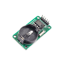
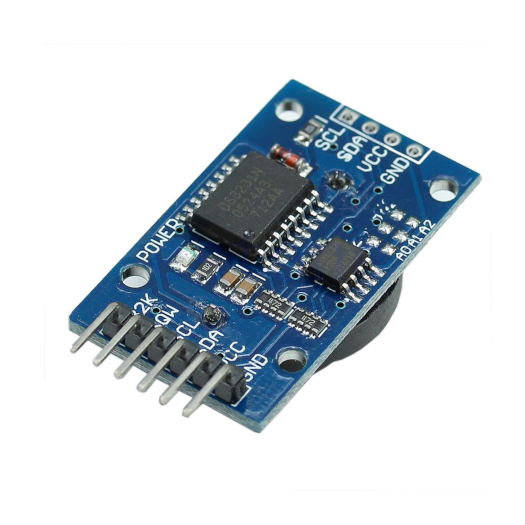
ESP32 DS1302 Real-Time Clock (RTC) Pinout, Wiring, ESP32 and more
Overview
The DS1302 is a cost-effective real-time clock module designed for accurate timekeeping. It operates on a 3-wire serial protocol and supports dual power supplies with a programmable trickle charger, making it suitable for embedded systems, IoT devices, and battery-backed applications.
About DS1302 Real-Time Clock (RTC)
The DS1302 is a low-power real-time clock (RTC) chip capable of maintaining accurate time and date, including leap year compensation up to 2100. It features built-in SRAM storage and a 3-wire serial interface, making it easy to integrate into time-sensitive applications.
⚡ Key Features
- Real-Time Clock Functionality – Tracks seconds, minutes, hours, day, month, and year.
- Integrated 31-Byte SRAM – Provides small data storage for system use.
- Dual Power Supply with Trickle Charger – Supports battery backup for continuous operation.
- 3-Wire Serial Interface – Ensures efficient communication with ESP32, Arduino, and other microcontrollers.
With its battery-backed operation and compact design, the DS1302 is perfect for low-power embedded systems, data loggers, and real-time event tracking. 🚀
Where to Buy DS1302 Real-Time Clock (RTC)


Prices are subject to change. We earn from qualifying purchases as an Amazon Associate.
DS1302 Datasheet and Technical Specifications
DS1302 Pinout Diagram
The VCC pin is used to supply power to the sensor, and it typically requires 3.3V or 5V (refer to the datasheet for specific voltage requirements). The GND pin is the ground connection and must be connected to the ground of your ESP32.
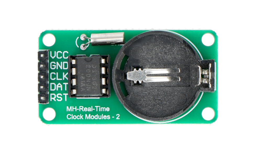
The DS1302 pinout is as follows:
- VCC1: Primary power supply input.
- VCC2: Backup power supply input.
- SCLK: Serial clock input for communication.
- I/O: Data input/output pin.
- RST: Reset input to enable communication.
- GND: Ground connection.
- X1: Connection for 32.768 kHz crystal oscillator.
- X2: Connection for 32.768 kHz crystal oscillator.
DS1302 Wiring with ESP32
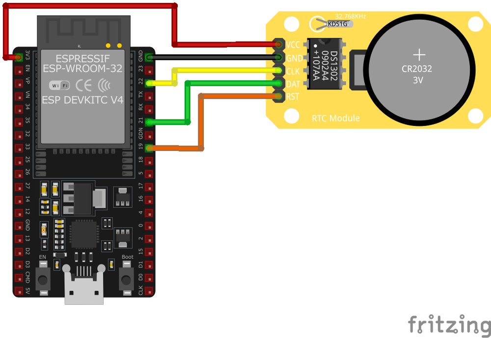
VCC1 to a 5V power supply, VCC2 to a backup battery or capacitor, GND to ground, SCLK to a GPIO pin for serial clock, I/O to a GPIO pin for data communication, and RST to another GPIO pin for enabling the chip. Ensure proper initialization in the microcontroller firmware.DS1302 Troubleshooting Guide
Common Issues
⏰ RTC Not Advancing Time Correctly
Issue: The DS1302 RTC module displays a constant time or advances time incorrectly.
Possible causes include insufficient power supply, incorrect wiring, or a defective module.
Solution: Ensure that the module is connected to a stable power source, with VCC connected to 5V and GND to ground. Verify that the CE, I/O, and SCLK pins are correctly connected to the appropriate digital pins on the microcontroller. If the problem persists, consider replacing the DS1302 module, as some units, especially from unreliable sources, may be faulty.
⚠️ Incorrect or Corrupted Date and Time Display
Issue: The DS1302 module displays incorrect or corrupted date and time information.
Possible causes include improper initialization, incorrect data retrieval methods, or communication errors.
Solution: Ensure that the RTC is properly initialized in your code, disabling write protection and setting the clock to run mode. Use reliable libraries and functions to set and retrieve time data. Verify that the communication between the microcontroller and the RTC is functioning correctly, and consider implementing error-checking mechanisms to detect and handle communication issues.
🔥 RTC Module Overheating
Issue: The DS1302 module becomes excessively hot during operation.
Possible causes include incorrect power connections, short circuits, or defective components.
Solution: Double-check all power connections to ensure they are correct, with VCC connected to the appropriate voltage and GND to ground. Inspect the module and wiring for any signs of short circuits or solder bridges. If the module continues to overheat, it may be defective and should be replaced.
🔄 Time Resets After Power Loss
Issue: The DS1302 RTC loses track of time after a power cycle.
Possible causes include a missing or depleted backup battery, or incorrect wiring of the backup power supply.
Solution: Install a backup battery (e.g., a CR2032 coin cell) to the VCC1 pin to maintain timekeeping during power loss. Ensure that the battery is fresh and properly connected. Verify that the VCC2 pin is connected to the main power supply, and that the module is configured to switch to the backup battery when the main power is unavailable.
Debugging Tips
🔍 Serial Monitor
Use the Serial Monitor to check for error messages and verify the sensor's output. Add debug prints in your code to track the sensor's state.
⚡ Voltage Checks
Use a multimeter to verify voltage levels and check for continuity in your connections. Ensure the power supply is stable and within the sensor's requirements.
Additional Resources
DS1302 Code Examples
Arduino Example
#include <DS1302.h>

DS1302 rtc(19, 21, 22); // RST, I/O, SCLK

void setup() {
    Serial.begin(9600);
    rtc.halt(false);
    rtc.writeProtect(false);
    rtc.setDateTime(2023, 12, 4, 14, 30, 0); // Set initial date/time: YYYY, MM, DD, HH, MM, SS
}

void loop() {
    DS1302::DateTime now = rtc.getDateTime();
    Serial.print("Time: ");
    Serial.print(now.hour);
    Serial.print(":");
    Serial.print(now.minute);
    Serial.print(":");
    Serial.println(now.second);
    Serial.print("Date: ");
    Serial.print(now.year);
    Serial.print("/");
    Serial.print(now.month);
    Serial.print("/");
    Serial.println(now.day);
    delay(1000);
}DS1302 library simplifies communication with the RTC. The setDateTime() function initializes the RTC with a specific date and time. In the loop(), the current date and time are fetched and displayed on the Serial Monitor.ESP-IDF Example
#include <stdio.h>
#include "driver/gpio.h"
#include "ds1302.h"

void app_main(void) {
    ds1302_config_t config = {
        .rst_pin = GPIO_NUM_19,
        .io_pin = GPIO_NUM_21,
        .sclk_pin = GPIO_NUM_22
    };
    ds1302_init(&config);
    ds1302_set_datetime(2023, 12, 4, 14, 30, 0);

    while (1) {
        ds1302_datetime_t now;
        ds1302_get_datetime(&now);
        printf("Time: %02d:%02d:%02d\n", now.hour, now.minute, now.second);
        printf("Date: %04d/%02d/%02d\n", now.year, now.month, now.day);
        vTaskDelay(pdMS_TO_TICKS(1000));
    }
}ds1302_get_datetime() function.ESPHome Example
uart:
  tx_pin: GPIO21
  rx_pin: GPIO22
  baud_rate: 9600

time:
  - platform: ds1302
    id: ds1302_time
    update_interval: 1s

sensor:
  - platform: custom
    lambda: |-
      auto my_sensor = new DS1302Sensor(id(ds1302_time));
      return {my_sensor};
    sensors:
- name: "DS1302 Date and Time"time platform is used to interact with the RTC, and a custom sensor is defined to periodically retrieve and display the date and time. The update interval is set to 1 second for regular updates.PlatformIO Example
platformio.ini
[env:arduino_uno]
platform = atmelavr
board = uno
framework = arduino
monitor_speed = 9600
PlatformIO Example Code
#include <DS1302.h>

DS1302 rtc(19, 21, 22); // RST, I/O, SCLK

void setup() {
    Serial.begin(9600);
    rtc.halt(false);
    rtc.writeProtect(false);
    rtc.setDateTime(2023, 12, 4, 14, 30, 0);
}

void loop() {
    DS1302::DateTime now = rtc.getDateTime();
    Serial.print("Time: ");
    Serial.print(now.hour);
    Serial.print(":");
    Serial.print(now.minute);
    Serial.print(":");
    Serial.println(now.second);
    Serial.print("Date: ");
    Serial.print(now.year);
    Serial.print("/");
    Serial.print(now.month);
    Serial.print("/");
    Serial.println(now.day);
    delay(1000);
}MicroPython Example
from machine import Pin
import time

# Pin definitions
CLK = Pin(22, Pin.OUT)  # Clock pin
DAT = Pin(21, Pin.INOUT)  # Data pin
RST = Pin(19, Pin.OUT)  # Reset pin

# DS1302 commands
READ_TIME = 0x81
WRITE_TIME = 0x80

def write_byte(byte):
    for i in range(8):
        CLK.value(0)
        DAT.value((byte >> i) & 1)
        CLK.value(1)

def read_byte():
    result = 0
    for i in range(8):
        CLK.value(0)
        if DAT.value():
            result |= (1 << i)
        CLK.value(1)
    return result

def set_time(year, month, day, hour, minute, second):
    RST.value(1)
    write_byte(WRITE_TIME)
    write_byte(second)
    write_byte(minute)
    write_byte(hour)
    write_byte(day)
    write_byte(month)
    write_byte(year - 2000)
    RST.value(0)

def get_time():
    RST.value(1)
    write_byte(READ_TIME)
    second = read_byte()
    minute = read_byte()
    hour = read_byte()
    day = read_byte()
    month = read_byte()
    year = read_byte() + 2000
    RST.value(0)
    return year, month, day, hour, minute, second

# Initialize DS1302
RST.value(0)
CLK.value(0)

# Set initial time
set_time(2023, 12, 4, 14, 30, 0)

# Loop to read time
while True:
    year, month, day, hour, minute, second = get_time()
    print(f"Time: {hour:02}:{minute:02}:{second:02}, Date: {year:04}/{month:02}/{day:02}")
time.sleep(1)set_time() function initializes the DS1302 with the provided date and time by writing data byte-by-byte. The get_time() function reads the current date and time by issuing the appropriate commands and parsing the returned bytes. The main loop continuously fetches and prints the time and date every second.Conclusion
The ESP32 DS1302 Real-Time Clock (RTC) is a powerful RTC sensor that offers excellent performance and reliability. With support for multiple development platforms including Arduino, ESP-IDF, ESPHome, PlatformIO, and MicroPython, it's a versatile choice for your IoT projects.
For optimal performance, ensure proper wiring and follow the recommended configuration for your chosen development platform.
Always verify power supply requirements and pin connections before powering up your project to avoid potential damage.
