
PCF8563 Real-Time Clock (RTC)
The PCF8563 is a low-power real-time clock/calendar with I2C interface, offering timekeeping functions, programmable clock output, alarm and timer features, and operating over a wide voltage range, making it ideal for portable and battery-powered applications.

PCF8563 pinout
The PCF8563 has 8 pins including I²C interface, oscillator connections, and optional interrupt/clock outputs.
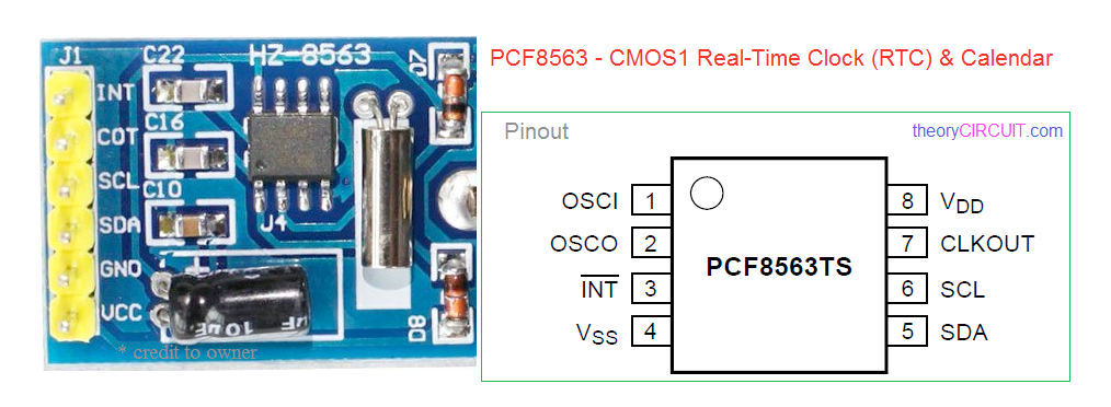
| Pin | Type | Description | Notes |
|---|---|---|---|
| OSCI | Oscillator | Oscillator input. Connect to one terminal of 32.768 kHz crystal. | Crystal capacitor integrated internally. |
| OSCO | Oscillator | Oscillator output. Connect to other terminal of 32.768 kHz crystal. | |
| INT | Interrupt | Interrupt output (open-drain, active low). Triggers on alarm or timer events. | Requires external pull-up resistor (~10kΩ). |
| VDD | Power | Power supply input (1.0V-5.5V). Wide voltage range for battery operation. | Ultra-low power consumption. |
| VSS | Power | Ground connection. Connect to system ground. | |
| SDA | I2C | I²C Serial Data Line. Bidirectional data communication. | Connect to ESP32 GPIO 21 (default SDA). |
| SCL | I2C | I²C Serial Clock Line. Clock signal for I²C communication. | Connect to ESP32 GPIO 22 (default SCL). |
| CLKOUT | Clock Output | Programmable clock output. Configurable frequency for external devices. | Optional - can provide clock signal to other components. |
I²C address: 0x51 (fixed)
Operating voltage: 1.0V-5.5V (wider than DS1307)
Ultra-low power consumption: ideal for battery-powered applications
Requires 32.768 kHz crystal (not included on basic modules)
Integrated oscillator capacitor (no external caps needed)
Alarm and timer functions with interrupt capability
Century flag for year tracking
Wiring the PCF8563 to ESP32
To interface the PCF8563 with an ESP32, connect VDD to 3.3V or 5V, VSS to ground, SDA to GPIO 21, SCL to GPIO 22, and attach a 32.768 kHz crystal between OSCI and OSCO.
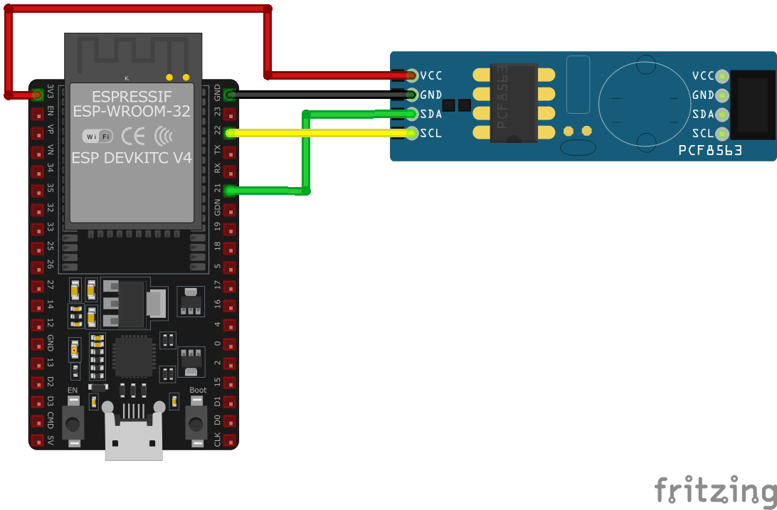
| PCF8563 pin | ESP32 pin | Purpose |
|---|---|---|
| VDD | 3.3V | Power supply. Use 3.3V for battery-powered applications. |
| VSS | GND | Ground connection. |
| SDA | GPIO 21 | I²C data line. Requires pull-up resistor (4.7kΩ typical). |
| SCL | GPIO 22 | I²C clock line. Requires pull-up resistor (4.7kΩ typical). |
| OSCI/OSCO | 32.768 kHz Crystal | Connect 32.768 kHz crystal between OSCI and OSCO pins. |
| INT | Optional GPIO | Interrupt output for alarm/timer events. Requires 10kΩ pull-up. · optional |
| CLKOUT | Optional | Programmable clock output for external devices. · optional |
I²C address: 0x51 (fixed, cannot be changed)
Add 4.7kΩ pull-up resistors on SDA and SCL lines
32.768 kHz crystal required for accurate timekeeping
For battery backup: add CR2032 battery to VDD (many modules have holder)
INT pin is open-drain - requires external pull-up resistor (~10kΩ)
Set initial time after first power-on or battery replacement
Lower power consumption than DS1307 - ideal for portable projects
Some modules include crystal and battery holder
PCF8563 code examples
// Requires library: "Rtc_Pcf8563"
#include <Wire.h>
#include <Rtc_Pcf8563.h>

Rtc_Pcf8563 rtc;

void setup() {
    Serial.begin(115200);
    Wire.begin(21, 22); // SDA: GPIO21, SCL: GPIO22
    rtc.initClock();
    // day, weekday, month, century (0 = 20xx), year (0-99)
    rtc.setDate(1, 2, 9, 0, 26);  // Tuesday 2026-09-01
    // second, minute, hour
    rtc.setTime(0, 30, 14);       // 14:30:00
}

void loop() {
    Serial.print("Time: ");
    Serial.print(rtc.getHour());
    Serial.print(":");
    Serial.print(rtc.getMinute());
    Serial.print(":");
    Serial.println(rtc.getSecond());
    Serial.print("Date: ");
    Serial.print(rtc.getDay());
    Serial.print("/");
    Serial.print(rtc.getMonth());
    Serial.print("/");
    Serial.println(rtc.getYear());
    delay(1000);
}
This Arduino sketch interfaces with the PCF8563 RTC module using the Rtc_Pcf8563 library and the specified pin configuration (SDA: GPIO21, SCL: GPIO22). In the setup(), the RTC is initialized and the date and time are set. The loop() retrieves and prints the current time and date to the Serial Monitor every second.
// Requires the esp-idf-lib PCF8563 driver from the ESP Component Registry:
//   idf.py add-dependency "esp-idf-lib/pcf8563^1.0.7"

#include <stdio.h>
#include <string.h>
#include <time.h>
#include "freertos/FreeRTOS.h"
#include "freertos/task.h"
#include "pcf8563.h"

#define SDA_GPIO GPIO_NUM_21
#define SCL_GPIO GPIO_NUM_22

void app_main(void)
{
    ESP_ERROR_CHECK(i2cdev_init());

    i2c_dev_t dev;
    memset(&dev, 0, sizeof(i2c_dev_t));
    ESP_ERROR_CHECK(pcf8563_init_desc(&dev, 0, SDA_GPIO, SCL_GPIO));

    while (1) {
        struct tm time;
        bool valid;
        if (pcf8563_get_time(&dev, &time, &valid) == ESP_OK)
            printf("%04d-%02d-%02d %02d:%02d:%02d (%s)\n",
                   time.tm_year + 1900, time.tm_mon + 1, time.tm_mday,
                   time.tm_hour, time.tm_min, time.tm_sec,
                   valid ? "valid" : "voltage low - time may be wrong");
        else
            printf("Could not read time from RTC\n");
        vTaskDelay(pdMS_TO_TICKS(1000));
    }
}
ESP-IDF ships no PCF8563 driver of its own, so this example uses the maintained esp-idf-lib PCF8563 driver from the ESP Component Registry. Install it into your project first with idf.py add-dependency "esp-idf-lib/pcf8563^1.0.7", then build as usual.
pcf8563_get_time() fills a standard struct tm and also reports a valid flag - the PCF8563 sets its voltage-low bit when backup power was lost, which means the stored time can no longer be trusted and the clock should be set again with pcf8563_set_time(). i2cdev_init() sets up the shared I2C layer used by all esp-idf-lib drivers.
i2c:
  sda: GPIO21
  scl: GPIO22

time:
  - platform: pcf8563
    id: rtc_time

text_sensor:
  - platform: template
    name: "PCF8563 Date and Time"
    lambda: |-
      char buf[20];
      auto now = id(rtc_time).now();
      if (!now.is_valid()) return {"unknown"};
      now.strftime(buf, sizeof(buf), "%Y-%m-%d %H:%M:%S");
      return {buf};
    update_interval: 1s
ESPHome's pcf8563 platform is a time source: it reads the RTC over I2C and can write the current time back with pcf8563.write_time. The custom sensor platform older examples used was removed from ESPHome in 2025 - the template text_sensor shown formats the RTC time for display instead.
[env:esp32dev]
platform = espressif32
board = esp32dev
framework = arduino
monitor_speed = 115200
lib_deps =
elpaso/Rtc_Pcf8563#include <Arduino.h>
#include <Wire.h>
#include <Rtc_Pcf8563.h>
Rtc_Pcf8563 rtc;
void setup() {
Serial.begin(115200);
Wire.begin(21, 22); // SDA: GPIO21, SCL: GPIO22
rtc.initClock();
// day, weekday, month, century (0 = 20xx), year (0-99)
rtc.setDate(1, 2, 9, 0, 26); // Tuesday 2026-09-01
// second, minute, hour
rtc.setTime(0, 30, 14); // 14:30:00
}
void loop() {
Serial.print("Time: ");
Serial.print(rtc.getHour());
Serial.print(":");
Serial.print(rtc.getMinute());
Serial.print(":");
Serial.println(rtc.getSecond());
Serial.print("Date: ");
Serial.print(rtc.getDay());
Serial.print("/");
Serial.print(rtc.getMonth());
Serial.print("/");
Serial.println(rtc.getYear());
delay(1000);
}This PlatformIO code interfaces with the PCF8563 RTC using the specified pin configuration (SDA: GPIO21, SCL: GPIO22). The RTC is initialized and configured in the setup(), while the loop() fetches and prints the current time and date every second.
from machine import I2C, Pin
import time

# PCF8563 I2C address
PCF8563_ADDRESS = 0x51

def bcd_to_decimal(bcd):
    return (bcd >> 4) * 10 + (bcd & 0x0F)

def decimal_to_bcd(decimal):
    return ((decimal // 10) << 4) | (decimal % 10)

def set_time(i2c, year, month, day, hour, minute, second):
    data = [decimal_to_bcd(second), decimal_to_bcd(minute), decimal_to_bcd(hour),
            0, decimal_to_bcd(day), decimal_to_bcd(month), decimal_to_bcd(year - 2000)]
    i2c.writeto_mem(PCF8563_ADDRESS, 0x02, bytes(data))

def get_time(i2c):
    data = i2c.readfrom_mem(PCF8563_ADDRESS, 0x02, 7)
    second = bcd_to_decimal(data[0] & 0x7F)
    minute = bcd_to_decimal(data[1] & 0x7F)
    hour = bcd_to_decimal(data[2] & 0x3F)
    day = bcd_to_decimal(data[3] & 0x3F)
    month = bcd_to_decimal(data[5] & 0x1F)
    year = bcd_to_decimal(data[6]) + 2000
    return year, month, day, hour, minute, second

# Initialize I2C
i2c = I2C(0, scl=Pin(22), sda=Pin(21))

# Set initial time
set_time(i2c, 2023, 12, 4, 14, 30, 0)

# Loop to read time
while True:
    year, month, day, hour, minute, second = get_time(i2c)
    print(f"Time: {hour:02}:{minute:02}:{second:02}, Date: {year:04}/{month:02}/{day:02}")
    time.sleep(1)
This MicroPython script communicates with the PCF8563 RTC over I2C using SDA (GPIO21) and SCL (GPIO22). The set_time() function initializes the RTC with the specified time and date, while the get_time() function reads and decodes the current time and date. In the loop, the script continuously fetches and prints the current time and date every second.
PCF8563 specifications
About the PCF8563
The PCF8563 is NXP’s low-power I2C real-time clock and calendar, answering on the bus at address 0x51 and covering the same seconds-through-year fields as the DS1307 and DS3231, plus a century flag, programmable clock output, and alarm and timer functions. It needs an external 32.768kHz crystal across its OSCI/OSCO pins to keep time, the same as the DS1307.
Its case for a spot on a project is power, not precision: typical backup current is only about 0.25uA at 3.0V, well below what the DS1307 or even the DS3231 draw in battery-backed standby, and it runs natively across a 1.0V to 5.5V range - so it works cleanly on a 3.3V ESP32 bus without the DS1307’s 5V-logic complications, and it can keep ticking off a coin cell for years. What it does not have is the DS3231’s temperature-compensated oscillator: like the DS1307 and DS1302, its accuracy rides on the external crystal, so expect the same tens-of-ppm-class drift rather than the DS3231’s roughly 1-minute-a-year figure.
That trade-off makes the choice fairly clean: pick the DS3231 when a project needs the clock to stay accurate for months without help, and pick the PCF8563 when the priority is squeezing the most runtime out of a small battery and an occasional NTP resync can absorb the drift.
PCF8563 troubleshooting
RTC Not Advancing Time Correctly
›
Issue: The PCF8563 RTC module displays a constant time or advances time incorrectly.
Possible causes include insufficient power supply, incorrect wiring, or a defective module.
Solution: Ensure that the module is connected to a stable power source, with VCC connected to 3.3V or 5V (depending on your module) and GND to ground. Verify that the SDA and SCL pins are correctly connected to the appropriate I2C pins on the microcontroller. If the problem persists, consider replacing the PCF8563 module, as some units may be faulty.
Incorrect or Corrupted Date and Time Display
›
Issue: The PCF8563 module displays incorrect or corrupted date and time information.
Possible causes include improper initialization, incorrect data retrieval methods, or communication errors.
Solution: Ensure that the RTC is properly initialized in your code, setting the correct time and date during setup. Use reliable libraries and functions to set and retrieve time data. Verify that the communication between the microcontroller and the RTC is functioning correctly, and consider implementing error-checking mechanisms to detect and handle communication issues.
RTC Module Overheating
›
Issue: The PCF8563 module becomes excessively hot during operation.
Possible causes include incorrect power connections, short circuits, or defective components.
Solution: Double-check all power connections to ensure they are correct, with VCC connected to the appropriate voltage and GND to ground. Inspect the module and wiring for any signs of short circuits or solder bridges. If the module continues to overheat, it may be defective and should be replaced.
Time Resets After Power Loss
›
Issue: The PCF8563 RTC loses track of time after a power cycle.
Possible causes include a missing or depleted backup battery, or incorrect wiring of the backup power supply.
Solution: Install a backup battery (e.g., a CR2032 coin cell) to the appropriate pins to maintain timekeeping during power loss. Ensure that the battery is fresh and properly connected. Verify that the module is configured to switch to the backup battery when the main power is unavailable.
Where to buy the PCF8563

Resources
Similar sensors


