KY-012 Active Buzzer Module
View on Amazon
Overview
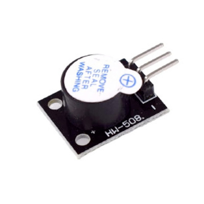
About KY-012 Active Buzzer Module
The KY-012 Active Buzzer Module is equipped with an active piezoelectric buzzer that emits a tone at approximately 2.5 kHz when powered. Unlike passive buzzers, this module does not require an external square wave signal; it generates sound as soon as a voltage of at least 3.3V is applied to its signal pin. Operating within a voltage range of 3.3V to 5V and drawing a maximum current of 30 mA, it produces a minimum sound output of 85 dB. This makes it suitable for applications requiring audible alerts, such as alarm systems and user notifications.
Get Your KY-012


💡 Prices are subject to change. We earn from qualifying purchases as an Amazon Associate.
KY-012 Specifications
Complete technical specification details for KY-012 Active Buzzer Module
📊 Technical Parameters
KY-012 Pinout
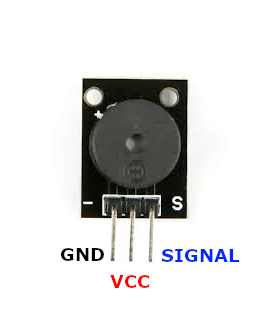
The **KY-012** is a 3-pin active piezoelectric buzzer module:
Visual Pinout Diagram
Pin Types
Quick Tips
**Interface**: Digital output (simple HIGH/LOW control),🔊 **Type**: Active buzzer (built-in oscillator)
**Frequency**: Fixed 2.5 kHz tone,⚡ **Power**: 3.3V to 5V, 30mA max current
**Volume**: Minimum 85 dB output,🎯 **Applications**: Alarms, alerts, notifications, simple audio feedback
Pin Descriptions
| Pin Name | Type | Description | Notes |
|---|---|---|---|
1 Pin (-) | Power | Ground connection | |
2 Pin (middle) | Control | Not connected | Leave unconnected (NC) |
3 Pin (S) | Communication | Signal/power input | Apply 3.3V or 5V to activate buzzer |
Wiring KY-012 to ESP32
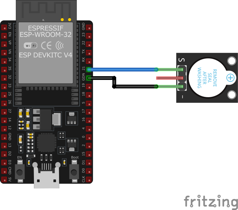
To interface the **KY-012** with an **ESP32** for simple buzzer alerts:
Visual Wiring Diagram
Connection Status
Protocol
Pin Connections
| KY-012 Pin | Connection | ESP32 Pin | Description |
|---|---|---|---|
1 Pin (-) Required | GND | Ground | |
2 Pin (S) Required | GPIO15 | Digital output (any GPIO) | |
3 Pin (middle) Optional | N/C | Not connected |
**Simple Control**: Just set GPIO HIGH to activate, LOW to stop
**GPIO Selection**: Any digital GPIO pin works, GPIO15 is just an example
**Voltage**: Use 3.3V GPIO output for ESP32 (sufficient for activation)
**Fixed Tone**: Cannot change frequency (use KY-006 passive buzzer for variable tones)
KY-012 Troubleshooting
Common issues and solutions to help you get your sensor working
Common Issues
Issue: The buzzer does not produce any sound when expected.
Solutions:
- Ensure the module is properly connected to the microcontroller, with the correct pins assigned.
- Verify that the signal pin is receiving the appropriate voltage (at least 3.3V).
- Check for any soldering issues or loose connections on the module.
Issue: The buzzer emits a continuous sound when it shouldn't.
Solutions:
- Ensure that the signal pin is not inadvertently set to HIGH in the code.
- Check for any short circuits or unintended connections that might cause the signal pin to remain HIGH.
Debugging Tips
Use the Serial Monitor to check for error messages and verify the sensor's output. Add debug prints in your code to track the sensor's state.
Use a multimeter to verify voltage levels and check for continuity in your connections. Ensure the power supply is stable and within the sensor's requirements.
Additional Resources
KY-012 Programming Examples
Ready-to-use code examples for different platforms and frameworks
int buzzer = 13;

void setup() {
    pinMode(buzzer, OUTPUT); // Initialize the buzzer pin as an output
}

void loop() {
    digitalWrite(buzzer, HIGH); // Turn the buzzer on
    delay(4000); // Wait for 4 seconds
    digitalWrite(buzzer, LOW); // Turn the buzzer off
    delay(2000); // Wait for 2 seconds
}
This Arduino code alternates the KY-012 buzzer on and off. The buzzer is connected to pin 13, which is set as an output. The buzzer is turned on for 4 seconds and then off for 2 seconds in a continuous loop.
#include <stdio.h>
#include "freertos/FreeRTOS.h"
#include "freertos/task.h"
#include "driver/gpio.h"

#define BUZZER_PIN GPIO_NUM_15

void app_main(void) {
    gpio_config_t io_conf = {
        .pin_bit_mask = (1ULL << BUZZER_PIN),
        .mode = GPIO_MODE_OUTPUT,
        .pull_up_en = GPIO_PULLUP_DISABLE,
        .pull_down_en = GPIO_PULLDOWN_DISABLE,
        .intr_type = GPIO_INTR_DISABLE
    };
    gpio_config(&io_conf);

    while (1) {
        gpio_set_level(BUZZER_PIN, 1); // Turn the buzzer on
        vTaskDelay(pdMS_TO_TICKS(4000)); // Wait for 4 seconds
        gpio_set_level(BUZZER_PIN, 0); // Turn the buzzer off
        vTaskDelay(pdMS_TO_TICKS(2000)); // Wait for 2 seconds
    }
}
This ESP-IDF code configures GPIO15 as an output to control the KY-012 active buzzer. The buzzer is turned on for 4 seconds and then off for 2 seconds in a loop.
output:
  - platform: gpio
    pin: GPIO15
    id: buzzer_output

switch:
  - platform: output
    name: "KY-012 Buzzer"
    output: buzzer_output
    turn_on_action:
      - output.turn_on: buzzer_output
      - delay: 4s
      - output.turn_off: buzzer_output
    turn_off_action:
      - output.turn_off: buzzer_output
This ESPHome configuration sets up the KY-012 active buzzer on GPIO15 using a simple GPIO switch. The buzzer can be toggled on and off through the ESPHome interface.
platformio.ini
[env:esp32]
platform = espressif32
board = esp32dev
framework = arduino
main.cpp
#include <Arduino.h>

#define BUZZER_PIN 15

void setup() {
    pinMode(BUZZER_PIN, OUTPUT);
}

void loop() {
    digitalWrite(BUZZER_PIN, HIGH); // Turn buzzer on
    delay(4000);
    digitalWrite(BUZZER_PIN, LOW); // Turn buzzer off
    delay(2000);
}
This PlatformIO code configures GPIO15 as an output to control the KY-012 active buzzer. The buzzer is turned on for 4 seconds and off for 2 seconds in an alternating cycle.
import machine
import time

BUZZER_PIN = machine.Pin(15, machine.Pin.OUT)

while True:
    BUZZER_PIN.value(1)  # Turn buzzer on
    time.sleep(4)        # Wait for 4 seconds
    BUZZER_PIN.value(0)  # Turn buzzer off
    time.sleep(2)        # Wait for 2 seconds
This MicroPython script configures GPIO15 as an output for the KY-012 active buzzer. It alternates the buzzer on and off in a cycle of 4 seconds on and 2 seconds off.
Wrapping Up KY-012
The ESP32 KY-012 Active Buzzer Module is a powerful KY-0xx module sensor that offers excellent performance and reliability. With support for multiple development platforms including Arduino, ESP-IDF, ESPHome, PlatformIO, and MicroPython, it's a versatile choice for your IoT projects.
Best Practices
For optimal performance, ensure proper wiring and follow the recommended configuration for your chosen development platform.
Safety First
Always verify power supply requirements and pin connections before powering up your project to avoid potential damage.
Ready to Start Building?
Now that you have all the information you need, it's time to integrate the KY-012 into your ESP32 project and bring your ideas to life!
Explore Alternative Sensors
Looking for alternatives to the KY-012? Check out these similar sensors that might fit your project needs.
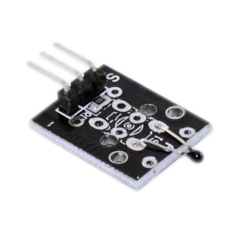
KY-013 Analog Temperature Sensor Module
The KY-013 is an analog temperature sensor module utilizing an NTC thermistor. It provides temperature measurements in the range of -55°C to...
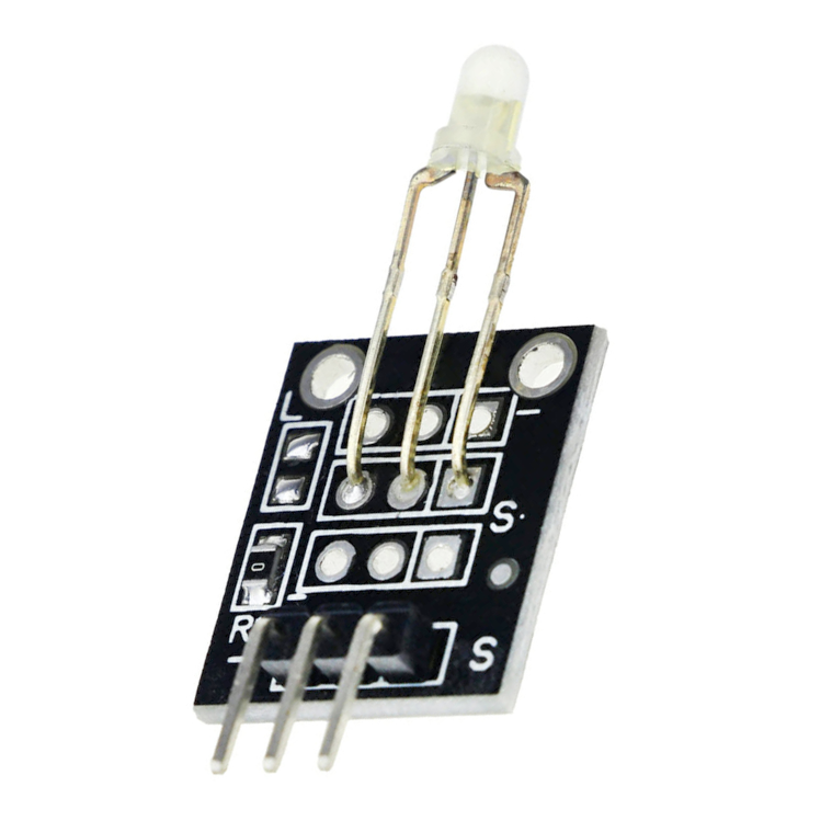
KY-029 Dual Color LED Module
The KY-029 is a dual-color LED module featuring a 3mm LED that emits red and green light. By adjusting the intensity of each color using...
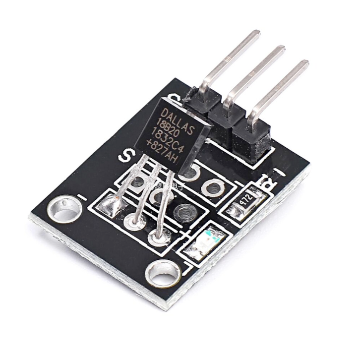
KY-001 Temperature Sensor Module
The KY-001 is a temperature sensor module that operates within a wide temperature range. It supports 1-Wire communication and is based on...


