
KY-035 Analog Hall Magnetic Sensor Module
The KY-035 is an analog Hall magnetic sensor module based on the AH49E linear Hall-effect sensor. It provides an analog output voltage proportional to the detected magnetic field strength and polarity, making it ideal for applications in motor control, position sensing, and magnetic field detection.

KY-035 pinout
The KY-035 is a 3-pin analog Hall effect sensor module:
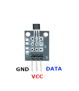
| Pin | Type | Description | Notes |
|---|---|---|---|
| - | Power | Ground connection | |
| middle | Power | Power supply | 3.3V to 5V |
| S | Communication | Analog signal output | Voltage proportional to magnetic field |
Interface: Analog linear Hall effect sensor
Sensor: AH49E linear Hall effect sensor IC
Output: Analog voltage proportional to magnetic field strength and polarity
Power: 3.3V to 5V operation
Polarity Detection: Output voltage changes based on North/South pole orientation
Range: Sensitive to magnetic fields from -100 to +100 Gauss
Applications: Motor position sensing, speed detection, proximity sensing, contactless switches
Wiring the KY-035 to ESP32
To interface the KY-035 with an ESP32 for analog magnetic field sensing:
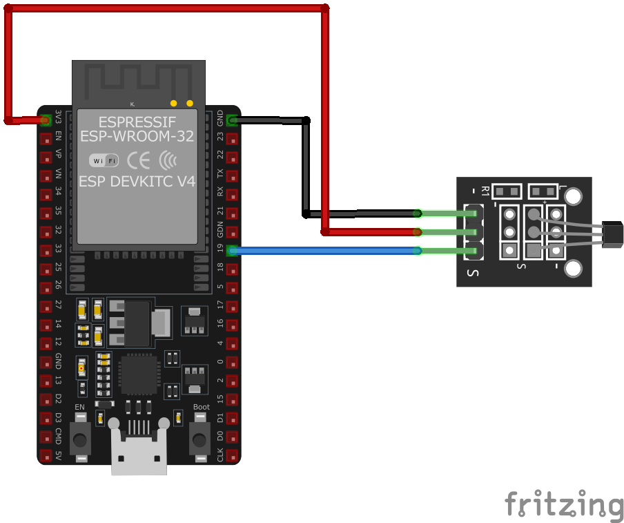
| KY-035 pin | ESP32 pin | Purpose |
|---|---|---|
| - | GND | Ground |
| middle | 3.3V | Power supply |
| S | GPIO34 | Analog input (ADC pin) |
Linear Response: Output voltage varies linearly with magnetic field strength
ADC Pins: Use GPIO32-39 for analog input on ESP32
Voltage: 3.3V recommended for ESP32 ADC compatibility
North Pole: Increases output voltage above baseline (~1.65V at 3.3V supply)
South Pole: Decreases output voltage below baseline
Baseline: ~50% of supply voltage when no magnetic field present
Sensitivity: ~1.4 mV/Gauss typical
Calibration: Read baseline value at startup (no magnet) for reference
KY-035 code examples
int sensorPin = 34; // KY-035 signal pin (GPIO34 / ADC1_CH6, matches the wiring above)

void setup() {
    Serial.begin(115200);
    Serial.println("KY-035 Magnetic Field Detection");
}

void loop() {
    int rawValue = analogRead(sensorPin);
    // ESP32 ADC: 12-bit (0-4095) at 3.3V reference
    float voltage = rawValue * (3.3 / 4095.0) * 1000; // Convert to millivolts
    Serial.print("Voltage: ");
    Serial.print(voltage);
    Serial.println(" mV");
    delay(1000);
}
The analog hall sensor is read on GPIO34 (ADC1_CH6, matching the wiring above) and the raw 12-bit value is converted to millivolts using the ESP32's 3.3V reference (raw * 3.3 / 4095 * 1000). With no magnetic field the output idles near mid-supply; it swings up or down depending on the field's polarity.
#include <stdio.h>
#include "freertos/FreeRTOS.h"
#include "freertos/task.h"
#include "driver/adc.h"

#define SENSOR_CHANNEL ADC1_CHANNEL_6 // GPIO34

void app_main(void) {
    adc1_config_width(ADC_WIDTH_BIT_12);
    adc1_config_channel_atten(SENSOR_CHANNEL, ADC_ATTEN_DB_11);

    printf("KY-035 Magnetic Field Detection\n");
    while (1) {
        int raw = adc1_get_raw(SENSOR_CHANNEL);
        float voltage = raw * (3.3 / 4095.0) * 1000; // Convert to millivolts
        printf("Voltage: %.2f mV\n", voltage);
        vTaskDelay(pdMS_TO_TICKS(1000));
    }
}
This ESP-IDF code configures ADC1 channel 6 (GPIO34) to read analog values from the KY-035 sensor. It converts the raw ADC value to voltage in millivolts and prints it to the console every second.
sensor:
  - platform: adc
    pin: GPIO34
    name: "KY-035 Magnetic Field Sensor"
    update_interval: 1s
    filters:
      - multiply: 3.3
      - lambda: |-
          return x * 1000;  // Convert to millivolts
This ESPHome configuration sets up the KY-035 sensor connected to GPIO34 as an ADC sensor. It reads the analog voltage every second, converts it to millivolts, and logs the value. The lambda function ensures the output is in millivolts for easier interpretation.
[env:esp32]
platform = espressif32
board = esp32dev
framework = arduino#include <Arduino.h>
#define SENSOR_PIN 34
void setup() {
Serial.begin(115200);
Serial.println("KY-035 Magnetic Field Sensor Test");
}
void loop() {
int raw_value = analogRead(SENSOR_PIN);
float voltage = raw_value * (3.3 / 4095.0) * 1000; // Convert to millivolts
Serial.print("Magnetic Field Voltage: ");
Serial.print(voltage);
Serial.println(" mV");
delay(1000);
}This PlatformIO code sets up GPIO34 as an analog input for the KY-035 sensor. It reads the raw ADC value, converts it to millivolts, and logs it to the serial monitor every second.
import machine
import time

SENSOR_PIN = machine.ADC(machine.Pin(34))
SENSOR_PIN.atten(machine.ADC.ATTN_11DB)

while True:
    raw_value = SENSOR_PIN.read()
    voltage = (raw_value / 4095) * 3300  # Convert to millivolts
    print("Magnetic Field Voltage:", voltage, "mV")
    time.sleep(1)
This MicroPython script configures GPIO34 as an ADC input for the KY-035 sensor. It reads the raw ADC value, converts it to millivolts, and prints it to the console every second.
KY-035 specifications
About the KY-035
The KY-035 uses the same AH49E-family linear Hall-effect sensor as the KY-024, but strips away everything else on that board: no LM393 comparator, no potentiometer, no digital output pin - just the bare Hall IC on a 3-pin header with a single analog signal. That signal still behaves the same way it does on the KY-024: it sits near mid-supply with no magnet present and swings up or down from there depending on which pole is nearby and how strong the field is, so polarity as well as strength is readable from a single ADC pin.
The tradeoff for the simpler board is that there’s no adjustable threshold and no digital trigger pin to fall back on - every reading has to be interpreted in software, typically by taking a baseline ADC value with no magnet present at startup and comparing later readings against it. For projects that want a ready-made on/off trigger alongside the analog reading, the KY-024’s comparator and pot do that job directly; pick the KY-035 when only the raw linear signal is needed and the extra parts on the KY-024 would go unused.
KY-035 troubleshooting
No Output Signal
›
Issue: The sensor does not provide any output signal.
Solutions:
- Verify that the module is properly powered with the correct voltage (3.3V to 5V).
- Ensure all connections are secure and correctly wired.
- Check for any damage to the sensor or module components.
Incorrect or Fluctuating Readings
›
Issue: The sensor outputs incorrect or unstable readings.
Solutions:
- Ensure that there are no external magnetic fields or electrical noise affecting the sensor.
- Use proper shielding and grounding techniques to minimize interference.
- Calibrate the sensor to account for any environmental factors.
Where to buy the KY-035

Resources
Similar sensors


