
SIM7600G LTE CAT1 Module
The SIM7600G is a versatile LTE CAT1 module that provides reliable communication capabilities for various IoT applications. Its compact design, high-speed data connectivity, and multiple interfaces make it an ideal choice for projects requiring cellular and GPS functionalities.

SIM7600G / SIM7600E pinout
The SIM7600G is a high-speed LTE CAT1 module with UART and USB:
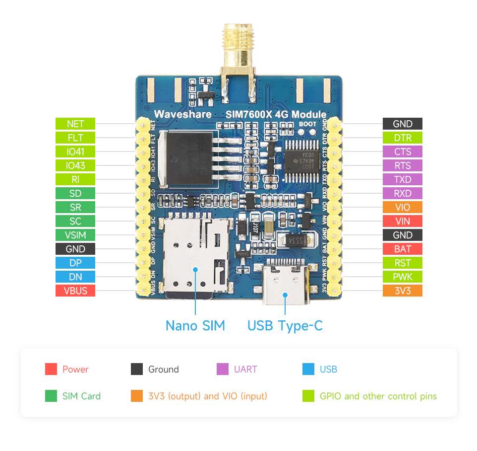
| Pin | Type | Description | Notes |
|---|---|---|---|
| VBAT | Power | Battery power input | 3.4V to 4.2V |
| GND | Power | Ground connection | |
| TXD | Communication | UART transmit | Module to MCU (connect to ESP32 RX) |
| RXD | Communication | UART receive | MCU to module (connect to ESP32 TX) |
| PWRKEY | Control | Power on/off control | Active low, pull low >500ms |
| NETLIGHT | Status | Network status LED | Blink pattern shows connectivity |
| STATUS | Status | Module power status | HIGH when module is powered |
| ANT_MAIN | RF | Main LTE/GSM antenna | 50Ω impedance |
| ANT_GPS | RF | GPS antenna | Active GPS antenna |
Networks: LTE CAT1, HSPA+, GSM, GPRS, EDGE
Speed: 10 Mbps downlink, 5 Mbps uplink (LTE CAT1)
Power: 3.4V-4.2V with peak 2A current
Interfaces: UART, USB 2.0, GPIO
Bands: Multi-band LTE-FDD/TDD support
Antennas: Dual antenna (LTE + GPS)
GPS: Built-in GPS/GLONASS/Galileo/BeiDou
SIM: Nano-SIM card slot
Applications: Industrial IoT, tracking, high-speed data
Wiring the SIM7600G / SIM7600E to ESP32
To interface the SIM7600G with an ESP32 via UART:
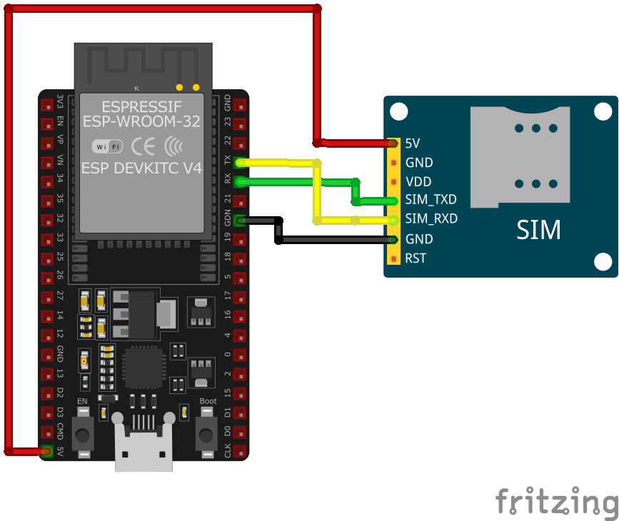
| SIM7600G / SIM7600E pin | ESP32 pin | Purpose |
|---|---|---|
| VBAT | External 3.7-4.2V | LiPo battery or regulated supply |
| GND | GND | Ground (shared with ESP32) |
| TXD | GPIO16 (RX2) | Module transmit to ESP32 receive |
| RXD | GPIO17 (TX2) | Module receive from ESP32 transmit |
| PWRKEY | GPIO5 | Power control (pull low >500ms) |
| ANT_MAIN | LTE Antenna | Main antenna connection |
| ANT_GPS | GPS Antenna | GPS antenna (optional) · optional |
Power: Use 3.7V LiPo or 4V regulated supply with 2A+ capability
Capacitors: Add 100µF + 1000µF low-ESR capacitors
Baud Rate: 115200 bps default (configurable)
PWRKEY: Pull low for >500ms to power on/off
Antennas: Use LTE CAT1 antenna (50Ω) and active GPS antenna
SIM Card: Insert nano-SIM with LTE data plan
High Speed: 10 Mbps downlink for fast data transfer
GPS: Multi-GNSS support (GPS/GLONASS/Galileo/BeiDou)
AT Commands: Standard AT command set
SIM7600G / SIM7600E code examples
// SIM7600G on ESP32 UART2: module TXD -> GPIO16 (RX2), RXD -> GPIO17 (TX2), PWRKEY -> GPIO5
#define PWRKEY_PIN 5
#define MODEM_BAUD 115200

HardwareSerial modem(2); // UART2

void powerOnModem() {
    pinMode(PWRKEY_PIN, OUTPUT);
    digitalWrite(PWRKEY_PIN, LOW);
    delay(1200); // Hold PWRKEY low to power the module on
    digitalWrite(PWRKEY_PIN, HIGH);
    delay(5000); // Give the module time to boot and register
}

void sendATCommand(const char *command) {
    modem.println(command);
    delay(500);
    while (modem.available()) {
        Serial.write(modem.read());
    }
}

void setup() {
    Serial.begin(115200);
    modem.begin(MODEM_BAUD, SERIAL_8N1, 16, 17); // RX=GPIO16, TX=GPIO17

    powerOnModem();

    Serial.println("Testing AT communication...");
    sendATCommand("AT");       // Should answer OK
    sendATCommand("ATI");      // Module identification
    sendATCommand("AT+CSQ");   // Signal quality
    sendATCommand("AT+CREG?"); // Network registration status
}

void loop() {
    // Bridge the Serial Monitor and the modem so you can type AT commands directly
    while (Serial.available()) modem.write(Serial.read());
    while (modem.available()) Serial.write(modem.read());
}
This sketch talks to the SIM7600G over the ESP32's second hardware UART (UART2, RX on GPIO16, TX on GPIO17) - the ESP32 has three hardware UARTs, so the AVR-style SoftwareSerial library is neither available nor needed. GPIO5 pulses the module's PWRKEY to power it on, then a few basic AT commands verify communication, signal quality and network registration. The loop bridges the Serial Monitor to the module so you can type further AT commands interactively. Power the module from a supply that can deliver its transmit-burst current - not from the ESP32's 3.3V regulator.
#include <stdio.h>
#include <string.h>
#include "driver/uart.h"
#include "driver/gpio.h"
#include "freertos/task.h"

#define TX_PIN 17
#define RX_PIN 16
#define PWRKEY_PIN 5 // GPIO5, matches the wiring above
#define UART_PORT UART_NUM_1

void init_uart() {
    uart_config_t uart_config = {
        .baud_rate = 115200,
        .data_bits = UART_DATA_8_BITS,
        .parity = UART_PARITY_DISABLE,
        .stop_bits = UART_STOP_BITS_1,
        .flow_ctrl = UART_HW_FLOWCTRL_DISABLE
    };

    uart_param_config(UART_PORT, &uart_config);
    uart_set_pin(UART_PORT, TX_PIN, RX_PIN, UART_PIN_NO_CHANGE, UART_PIN_NO_CHANGE);
    uart_driver_install(UART_PORT, 1024, 0, 0, NULL, 0);
}

void power_on_sim7600g() {
    gpio_set_direction(PWRKEY_PIN, GPIO_MODE_OUTPUT);
    gpio_set_level(PWRKEY_PIN, 0);
    vTaskDelay(1000 / portTICK_PERIOD_MS); // Hold PWRKEY low for 1 second
    gpio_set_level(PWRKEY_PIN, 1);
    vTaskDelay(5000 / portTICK_PERIOD_MS); // Wait for the module to initialize
}

void app_main(void) {
    init_uart();
    power_on_sim7600g();

    char *test_cmd = "AT\r\n";
    uart_write_bytes(UART_PORT, test_cmd, strlen(test_cmd));

    while (true) {
        char data[128];
        int len = uart_read_bytes(UART_PORT, data, sizeof(data), 100 / portTICK_PERIOD_MS);
        if (len > 0) {
            data[len] = '\0';
            printf("Response: %s\n", data);
        }
        vTaskDelay(1000 / portTICK_PERIOD_MS);
    }
}
This ESP-IDF example initializes UART communication with the SIM7600G module and powers it on using the PWRKEY pin (GPIO4). The UART interface is configured with GPIO17 as TX and GPIO16 as RX. An AT command is sent to test communication, and responses from the module are printed to the console. Additional functionalities, such as SMS, GNSS data retrieval, or LTE-based internet connectivity, can be implemented.
uart:
  tx_pin: GPIO17  # module RXD
  rx_pin: GPIO16  # module TXD
  baud_rate: 115200

# ESPHome's sim800l component speaks the generic SIM AT command set, which these modules share for SMS
sim800l:
  on_sms_received:
    - logger.log:
        format: "Received '%s' from %s"
        args: [ 'message.c_str()', 'sender.c_str()' ]
ESPHome has no dedicated LTE-modem component, and the custom platform older examples used was removed in 2025. The sim800l component speaks the generic SIM AT command set for SMS, which the SIM7600G shares - wire UART2 as shown (115200 baud) and you get on_sms_received plus sim800l.send_sms actions. Data connectivity (LTE networking) is outside ESPHome's scope.
[env:sim7600g]
platform = espressif32
board = esp32dev
framework = arduino
monitor_speed = 115200#include <HardwareSerial.h>
#include <Arduino.h>
HardwareSerial sim7600g(1);
#define PWRKEY 4
void power_on_sim7600g() {
pinMode(PWRKEY, OUTPUT);
digitalWrite(PWRKEY, LOW);
delay(1000); // Hold PWRKEY low for 1 second
digitalWrite(PWRKEY, HIGH);
delay(5000); // Wait for initialization
}
void setup() {
Serial.begin(115200);
sim7600g.begin(9600, SERIAL_8N1, 16, 17); // RX, TX
power_on_sim7600g();
// Test AT command
sim7600g.println("AT");
delay(1000);
while (sim7600g.available()) {
Serial.write(sim7600g.read());
}
// Send SMS
sim7600g.println("AT+CMGF=1"); // Set SMS to text mode
delay(1000);
sim7600g.println("AT+CMGS=\"+1234567890\""); // Replace with recipient's number
delay(1000);
sim7600g.print("Hello from SIM7600G");
sim7600g.write(26); // CTRL+Z to send SMS
delay(5000);
}
void loop() {
// Handle incoming data or other functionalities
}This PlatformIO code interfaces with the SIM7600G module using HardwareSerial on an ESP32. The power_on_sim7600g function toggles the PWRKEY pin (GPIO4) to activate the module. The AT command is sent to test communication, and SMS functionality is implemented in the setup. Additional functionalities, like GNSS data retrieval or LTE-based internet connectivity, can be added in the loop.
from machine import UART, Pin
import time

# Initialize UART
uart = UART(2, baudrate=115200, tx=17, rx=16)
pwrkey = Pin(5, Pin.OUT)  # PWRKEY, matches the wiring above

def power_on_sim7600g():
    pwrkey.value(0)
    time.sleep(1)  # Hold PWRKEY low for 1 second
    pwrkey.value(1)
    time.sleep(5)  # Wait for module to initialize

def send_at(command):
    uart.write(command + '\r\n')
    time.sleep(1)
    while uart.any():
        print(uart.read().decode('utf-8'), end='')

# Power on the module
power_on_sim7600g()

# Test communication
send_at('AT')

# Send SMS
send_at('AT+CMGF=1')  # Set SMS to text mode
send_at('AT+CMGS="+1234567890"')  # Replace with recipient's number
uart.write("Hello from SIM7600G" + chr(26))
This MicroPython code communicates with the SIM7600G module over UART. The power_on_sim7600g function activates the module using the PWRKEY pin (GPIO4). The send_at function sends AT commands and prints the responses. The script initializes the module, tests communication, and demonstrates how to send an SMS. Additional logic for handling GNSS or LTE-based internet connectivity can be added.
SIM7600G / SIM7600E specifications
About the SIM7600G / SIM7600E
The SIM7600G name is worth reading carefully before buying: the plain SIM7600G / SIM7600E (the module this page covers) is an LTE Cat 1 part - 10 Mbps downlink, 5 Mbps uplink, matching the A7670 - while the very similarly named SIM7600G-H is a different, Cat 4 module rated for up to 150 Mbps downlink. The two get mixed up constantly in listings and forum posts, so it’s worth confirming which SKU a given board or breakout actually carries before assuming a spec applies.
What the Cat 1 SIM7600G/E does offer is a genuinely broad fallback chain: LTE-FDD and LTE-TDD, HSPA+/UMTS (3G, now largely sunset across the module’s core markets), and GSM/GPRS/EDGE (2G) underneath that. Unlike the LPWA parts in this lineup - SIM7000 and SIM7080G - it supports actual voice calls alongside data, which is the main reason to reach for it over a cheaper Cat-M1/NB-IoT module: a project that needs SMS, phone calls and real internet bandwidth together, with a network fallback if LTE coverage is thin, is what this module is for. Multi-constellation GNSS (GPS/GLONASS/Galileo/BeiDou) shares the same UART.
TinyGSM’s supported-modem list names SIM7600C and SIM7600E specifically; the SIM7600G registers and works the same way in practice since it speaks the same AT command set. As with the rest of this family, the module needs a supply that can deliver a multi-amp burst during transmission - running it off the ESP32’s own 3.3V regulator is the most common cause of random resets and failed network registration.
SIM7600G / SIM7600E troubleshooting
Module Fails to Power On
›
Issue: The SIM7600G module does not power up or respond to commands.
Possible causes include insufficient power supply, incorrect wiring, or faulty hardware.
Solution: Ensure the module is connected to a stable power source within the recommended voltage range of 3.4V to 4.2V. Verify that all connections are secure and correctly configured. If the problem persists, consider testing the module with a different power source or replacing it.
SIM Card Not Recognized
›
Issue: The module fails to detect or register the SIM card.
Possible causes include improper SIM card insertion, unsupported SIM card type, or SIM card lock.
Solution: Ensure the SIM card is properly inserted into the module's SIM card slot and is compatible with the GSM network. Verify that the SIM card is active and unlocked. If necessary, test the SIM card in another device to confirm its functionality.
Poor Network Signal or Connectivity Issues
›
Issue: The module experiences weak signal strength or fails to maintain a stable network connection.
Possible causes include improper antenna connection, environmental interference, or network coverage limitations.
Solution: Ensure the GSM antenna is securely connected to the module and positioned for optimal signal reception. Avoid placing the module near sources of electromagnetic interference. Check the network coverage in your area to ensure adequate signal strength.
AT Commands Not Responding
›
Issue: The module does not respond to AT commands sent from the microcontroller or computer.
Possible causes include incorrect baud rate settings, faulty serial connections, or improper command syntax.
Solution: Verify that the baud rate of the module matches that of the microcontroller or computer; the default baud rate is 115200 bps. Check that the TX and RX lines are correctly connected and that there are no loose connections. Ensure that AT commands are correctly formatted and terminated with a carriage return.
GPS Functionality Not Working
›
Issue: The SIM7600G module fails to acquire GPS signals or provide location data.
Possible causes include improper antenna connection, obstructed view of the sky, or GPS functionality not enabled.
Solution: Ensure the GPS antenna is properly connected and has a clear view of the sky to receive satellite signals. Verify that the GPS functionality is enabled by sending the appropriate AT commands to power on the GPS engine.
Where to buy the SIM7600G / SIM7600E

Resources
Similar sensors


