

5 Channel RGB + CCT LED Strip control with ESP32 and WLED
Controlling 5 Channels RGB + CCT LED Strip with Wemos ESP32 D1 Mini and WLED. 5-in-1 LED Strip RGB. + Cold White + Warm White. Synchronize multiple controllers.
When I started improving my desk setup, I wanted to add some LED lights behind the desk. Since I use this desk mostly for work, I wanted to have Cold White and Warm White colors for sure. But I also didn’t want to miss on the fancy RGB lights, especially when I use the desk for gaming.
That is how I chose to use the 5 channels LED Strip - Red, Green, Blue, Cold White and Warm White (Also known as the RGB + CCT LED Strip or 5-in-1 LED Strip), but I quickly realized controlling these strips is not as easy as controlling some addressable LED strips, such as WS2812B. To control the 5-in-1 LED Strip, we need to use MOSFETs.
Moreover, since we chose the 12V LED Strip, but would like to use one power source for both the LED Strip and ESP32 controller, we will need to step down the 12V power supply voltage to 5V suitable for the ESP32 D1 Mini> board.
With all these requirements, we will surely need to design a custom PCB board, right? Well not quite so, as the espthings.io comes to rescue. While we still need to build the board, the design is already there, which is a huge part of a custom PCB.
Building the Hardware #
For this tutorial, we will be using the DIY controller ET-AL01 from espthings.io. We chose this controller, because it follows all the recommendations for controlling LED strips with ESP32, ability to operate at 12V to 24V and most importantly provides 5 channels.
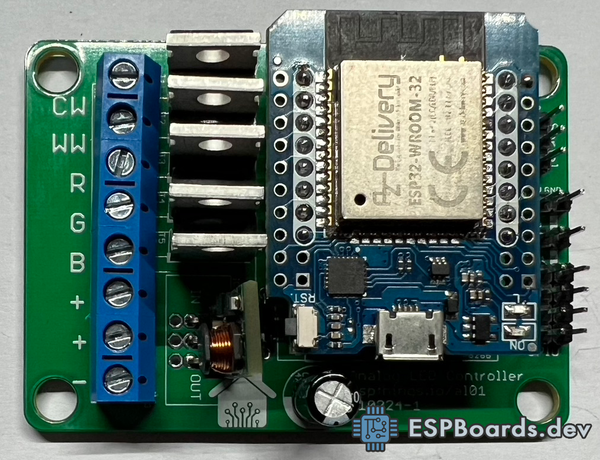
Moreover, it uses the popular ESP32 development board with a predefined form factor - the D1 Mini. These boards are widely available as original or more often clones from Amazon or Aliexpress. We already have a few at home, so that fits perfectly.
Bill of Materials #
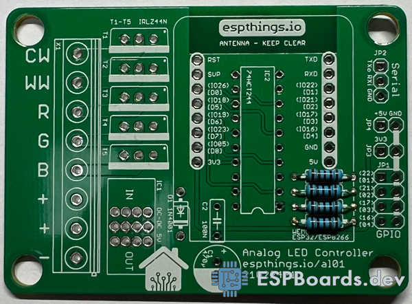
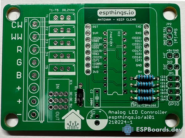
Below you can find the full list of parts needed to build your own custom PCB 5 Channels LED Controller with ESP32.

You can find each item in the picture above by the color code in the table. All the parts are widely available on the market and can be easily bought from Amazon or Aliexpress. The Custom PCB Board must be bought from PCBWay - in this way, you will support the creators of this board design - espthings.io.
| PCB Reference | Qty | Description | Link | |
|---|---|---|---|---|
| - | 1 | Custom PCB - ET-AL01 | PCBWay | |
| WEMOS1 | 1 | ESP32 D1 Mini |    | |
| WEMOS1 | 2 | 2.54mm Pin Header Female 1x8 | | |
| R1, R2, R3, R4 | 4 | 1K Resistors | | |
| D1 | 1 | 1N4001 Rectifier Diode | | |
| T1, T2, T3, T4, T5 | 5 | IRLZ44N or similar MOSFETs | | |
| X1 | 4 | 5mm Pitch Screw Terminal Block 2 Pole | | |
| IC1 | 1 | Step-down Buck converter 8-32V in, 5V out | | |
| IC2 | 1 | 74HCT244 | | |
| C1 | 1 | Aluminum Electrolytic Capacitor 470µF, 16V, 6mm diameter, 2.54mm pitch | | |
| C2 | 1 | Ceramic Capacitor 0.1µF | | |
| JP1, JP2, JP3, JP4 | 1 | Male pin headers. 2.54mm pitch 1x40 (JP1 - 1x3, JP2, JP3 - 1x2, JP4 - 2x 1x4) | |
While it is often difficult to order these parts online by one, they usually come in packs of 5, 10 or more. However, if you buy these packs, there will be leftover parts that you can use in your next project since those parts are quite common and are often used in different microcontroller projects.
The above were all the required components to build an LED Controller. However, for the whole project, you will need some other things, listed below.
| Image | Name | Link |
|---|---|---|
 | 12V RGB + CCT Led Strip | |
 | 12V Power Supply | |
 | 5.5mm x 2.1mm DC Power Supply Jack Socket | |
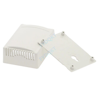 | 76 x 56 x 29mm Box Enclosure Case | |
Tools #
Apart from the materials, you will also need some tools for this project.
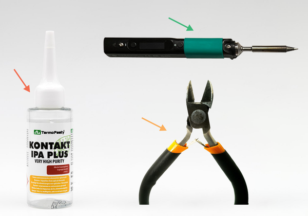
- Solder Iron - We are using the Pine64 Pinecil, but any solder iron will work.
- Wire cutter (Optional) - Any wire cutter will work. Used for cutting the excess legs from soldered THT (Through-hole technology) components.
- ISO Alcohol (Optional) - Isopropyl alcohol or IPA Alcohol. Used for easy cleaning of excess flux left on PCB after soldering.
Putting the Parts Together #
After sorting the components, start soldering the lowest components first. You can follow our steps below, which we found to be the easiest to deal with.
- Solder the resistors
Insert the resistors in places marked as R1, R2, R3, R4. The side of the resistor you insert does not matter here, but it is a good practice to add all resistors on the same side.
Solder resistors to the PCB board and cut the excess legs.
- Solder the Rectifier Diode
Insert the diode in the place marked as D1 (1N4001). Make sure to align the white strip on the diode with the with strip on the PCB board.
Solder the diode to the PCB board and cut the excess legs.
- Solder SN74HCT244N
Insert the SN74HCT244N to the PCB board spot marked as "74HCT244". Make sure to align the notch (cutout) with a marking on the PCB board!

Solder the SN74HCT244N to the PCB board and cut the excess legs.
- Solder the Male Pin Headers
Take the 1x40 Male Pin Header and cut it as follows:
- 2pcs. 1x2
- 1pcs. 1x3
- 2pcs. 1x4

Take the two 1x4 pieces insert them in the place marked as JP1 and solder them to the PCB. Take the one 1x3 piece and insert them in the place marked as JP2, solder it to the PCB. Take the two 1x2 pieces and insert them at paces marked as JP3 and JP4, solder them to the PCB.
- Solder the Female Pin Headers
Take the 2 pieces of 1x8 Female Pin Headers and insert them into the place marked as WEMOS1 on the PCB. For easier soldering, we recommend following the tutorial on espthings.io, where they use some additional Male Pin Headers to easily align the Female Headers to fit the ESP32 Board perfectly.

- Solder the Capacitors
First, take the 0.1µF Ceramic Capacitor and insert it into the C2 marked place on the PCB. Align the text "104" on the capacitor with the C2 marking text on the PCB board. Solder the capacitor and cut the excess legs.
Then take the 470µF Aluminum Electrolytic Capacitor and insert it into the C1 marked place on the PCB. Align the white line on the capacitor with the white side on the C1 circle. Solder the capacitor and cut the excess legs.

- Solder the Screw Terminals
Take the 4 pieces of 2 pole screw terminals and join them together - one side of the terminal should have a nub and another side should have a recess that is used to join the terminals together.
Insert the joined terminals into the PCB board in the spot marked as X1. Align the terminal so the wire inserts would be on the side with text (CW WW R G B + + -).
Solder the screw terminals to the PCB.
- Solder the IRLZ44N MOSFETs
Take 5 pieces of IRLZ44N MOSFETs and insert them into the PCB board spots marked as T1, T2, T3, T4, T5. Align the side with a heatsink with the white line on the PCB board print.
Solder the MOSFETs to the PCB.
- Solder the Step-down Buck Converter
Take the 8-32V in, 5V out Step-Down Buck Converter and insert it in the PCB spot marked as IC1. Note the IN and OUT sides when aligning the buck converter.
You can select one of the 4 spots to insert the buck converter. Select the one that suits you best, while making sure the buck converter's height does not exceed the height of MOSFETs! This is important if you are planning to insert the PCB Controller into a case later.

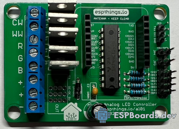
Congratulations! You have soldered all the required components to the custom PCB ET-AL01 RGB CCT LED Controller.
Preparing the ESP32 D1 Mini Development Board #
High chances are, you have received your ESP32 D1 Mini Development board unsoldered, as shown below.
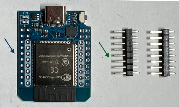
Take the 2 pcs. of 1x8 Male Pin Headers and put them in the white spots on the ESP32 D1 Mini board. To align pins more easily, try putting the pin headers in the breadboard, before soldering.

Solder the pins to the ESP32 board, make sure all the pins are soldered correctly and there are no bridged gaps between pins. Clean the excess flux with ISO Alcohol.
Software #
WLED is a popular open-source library that allows you to control addressable LED strips using your smartphone or a web browser. It supports a variety of addressable LED strips, including RGB + CCT.
WLED allows controlling multiple LED Strips with one app and synchronizing all your lights together. WLED also provides an interface for easy installation to ESP32 board, web interface and mobile (iOS/Android) applications, which we are going to use for this tutorial.
Installing WLED Firmware #
Connect your D1 Mini ESP32 board to the computer
Open WLED Install Web Page
Using Chrome Desktop, Microsoft Edge or other browsers that support website communication with serial devices, open the WLED Installer.
In case you cannot use the browser with serial device support, you can flash the image to ESP32 using esptool, following WLED official instructions.
- Install WLED to ESP32
Select a version and click Install. The popup should appear near the address bar, showing all available serial port devices.
Select your ESP32 board and click “Connect”. If you are not sure which device is your ESP32 board, try unplugging it from the USB and plugging back again.

When the browser connects to the ESP32 board, click “Install WLED” and confirm the installation.
The WLED installer will erase the ESP32 and install WLED software. You should see progress in percentage on the screen. After a few minutes, the installation should be done and you should see a confirmation message.
Click "Next" and connect the new WLED instance to your home WiFi by selecting your WiFi name, entering your WiFi password and clicking "Connect".
You should see a message "Device connected to the network!". Click on "Visit Device", it will open your new WLED instance Dashboard in the browser. Take note of the IP in the address bar.
Adding to Home Assistant #
Alternatively, you can easily add your new WLED instance to an existing Home Assistance server. If you do not have Home Assistance yet, but would like to start using it, check our post "Home Assistant in Docker Containers".
In the WLED Install website, click "Add to Home Assistant". A new tab will open. Enter your Home Assistant URL (for example "http://homeassistant.local:8123") in the text field and click "Save". Your Home Assistant instance will open where you can finish the setup.
Configuring WLED #
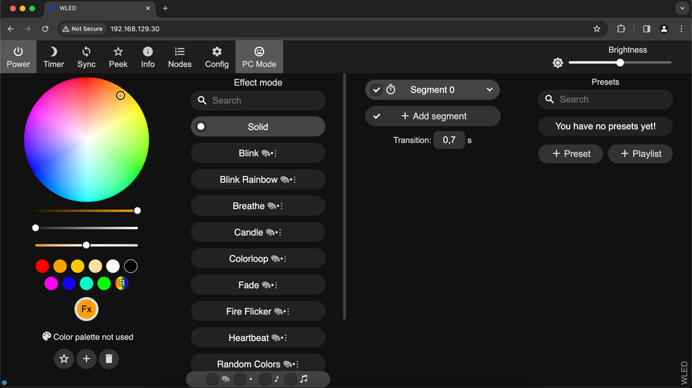
In the WLED Dashboard, click “Config” and select “LED Preferences”
Scroll down to the “Hardware Setup” section and under “LED Outputs”, select “PWM RGB+CCT”. Bellow, under “GPIOs”, enter pins as follows: “19”, “23”, “18”, “5”, “26”.

Click “Save” on top. The ESP32 board will restart and new settings will be applied.
We are ready with the firmware part.
Connecting Everything Together #
- Connect ESP32 D1 Mini to the PCB Board
Note the direction of the ESP32 board! The easiest part to identify is the Antenna.
- Connect wires to the PCB Board
Connect the Power socket - Black wire to the bottom pin, marked as (-), Red wire to the pin marked as (+)
Connect 6 Wires for LED Strip - +12V, and 5 wires for different colors - Red, Green, Blue, Cold White, and Warm White.

Solder the 6 wires to the corresponding pins on the RGB+CCT Led Strip.
Testing the 5-in-1 LED Strip #
Finally, connect the power supply to the Custom PCB LED Controller (Always make sure the USB port on the ESP32 board is disconnected from power, before connecting the LED Power Supply!)
Open the WLED Dashboard or WLED Android/iOS App and try changing the color. You should be able to select and see the LED Strip glow up in Red, Green and Blue colors from the color picker.
To test the Cold and Warm Whites, move the first slider below the color picker (Value/Brightness) to the left to turn off color LEDs and move the second slider (White Channel) to the right to turn on White LEDs. Move the third slider (White Balance) to left for Warm White or to the right for Cold White.
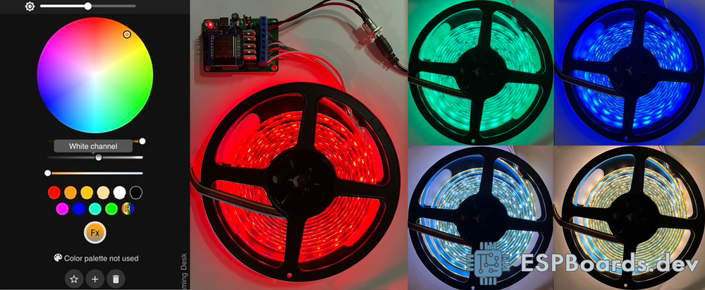
As you can see in the picture above, we have all 5 channels on our LED Strip working - Red, Green, Blue, Warm White and Cold White.
Useful links #
- ESP32 RGB LED Controller with Color Picker over WebSockets - Custom browser-based LED controller
- APA102, WS2812, SK6812 Addressable LED Strips Evolution - Want addressable LED Strip? Choose the one that suits your project best.
Conclusion #
Controlling 5 channels RGB + CCT Led Strip with ESP32 is not a very straightforward process, but neither is very complicated. Especially with the ET-AL01 Led Controller design from espthings.io, we can easily build the controller ourselves.
With the capabilities of controlling 5 channels, 12V LED Strip, while stepping down the voltage to 5V for ESP32 board (meaning we can use only one +12V power supply), exposed GPIOs with pin headers for additional features and all the recommended practices for controlling LED strips with ESP32, the ET-AL01 controller is a great choice.
Build a few of these controllers, install WLED software on them and you will have a great 5-in-1 LED Strip system controller in no time. With the help of WLED, all of the strips can be synchronized to be controlled by one device and one input!