
ESP32 38-Pin DevKit (Generic Clone) is a development board based on the ESP32 microcontroller using XTENSA architecture.
This board features a maximum CPU frequency of 240 MHz and 4MB flash memory.
About ESP32 38-Pin DevKit (Generic Clone)
✅ How to Identify Which Board You Have
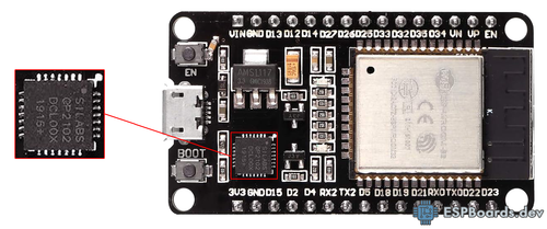
1. Check the USB-to-Serial ChipLook near the USB port for a square or rectangle IC with one of these labels:
- CH340C / CH340G → Most common on cheap clones. Rectangle chip.
- CP2102 → Common on mid-range boards. Square chip.
- CH9102F → Newer chip, similar to CP2102. Square chip.
- FT232RL → Less common but still found. Rectangle chip.
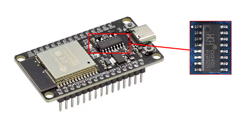

If you want to know more about USB-to-Serial chips, check out this detailed guide.
2. Count the Pins📏 38-pin boards are wider "NodeMCU-32S" style boards with 19 pins per side.
If you have 30 pins, check out the 30-pin variant guide instead.
- AMS1117 → Older clones (gets hot under load)
- Usually comes in a larger SOT-223 package with a flat metal tab (heatsinkable)
- Often has "AMS1117" or "1117/3.3" printed directly on the chip
- If you see a chunky 3-lead component with a metal tab near the USB port, it's likely AMS1117
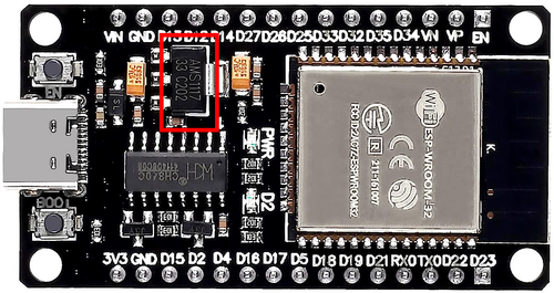
- ME6211 / HT7333 → Newer low-dropout regulators (better efficiency)
- Typically comes in small SOT-89 or SOT-23 packages (much smaller than SOT-223)
- If it's a tiny 3-pin SMD component next to the input capacitors, it's likely HT7333
- May have short marking codes that are harder to read
💡 Tip: Some boards print the regulator type on the silkscreen (check the board's underside or near the regulator for labels like "AMS1117" or "HT7333").
4. Look for Common LabelsMany 38-pin boards are labeled as:
- NodeMCU-32S → Very common CP2102-based boards
- ESP32 DevKit V1 → Generic label, various USB chips
- ESP-WROOM-32 → Refers to the WiFi module, not the board itself
✨ Key Advantages Over 30-Pin Boards
- More GPIOs exposed: 38 pins vs 30 pins means access to GPIO6-11 (though still not recommended for general use)
- VIN pin exposed: Can power from external 5V source without USB
- Better breadboard compatibility: Wider spacing works better with some breadboards
- More ground pins: Better for power distribution in complex projects
⚠️ Important Notes
- 38 pins total → More GPIOs than 30-pin variant, but still avoid GPIO6-11 (flash pins)
- Some boards label ADC pins as
VP,VN,SVP,SVNinstead of GPIO numbers - Driver installation required for CH340 chips (automatic on most modern systems)
- Strapping pins (GPIO0, GPIO2, GPIO12, GPIO15) must be in correct state during boot
- Wider board requires more breadboard space (may not fit standard 400-point breadboards)
Where to Buy ESP32 38-Pin DevKit (Generic Clone)

Starting from
4-7$ per unit


Prices are subject to change. We earn from qualifying purchases as an Amazon Associate.
Technical Specifications
Complete technical specification details for ESP32 38-Pin DevKit (Generic Clone)
USB
Connectivity
Microcontroller
✨ Features & Pins
Quick Setup
Copy-paste configs for ESP32 38-Pin DevKit (Generic Clone) - auto‑generated from this board's exact hardware specs.
In Arduino IDE 2 select Esp32 Dev from the esp32 by Espressif package. In PlatformIO use board = esp32dev. ESP32 · 240 MHz · 4MB · DIO.
In Arduino IDE 2, open Boards Manager, search "esp32" by Espressif and install it. Then go to Tools → Board and select "Esp32 Dev" for the ESP32 38-Pin DevKit (Generic Clone).
ESP32 38-Pin DevKit (Generic Clone) Board Dimensions
Physical measurements for ESP32 38-Pin DevKit (Generic Clone)
ESP32 38-Pin DevKit (Generic Clone) Pinout Diagram
Complete pin reference for ESP32 38-Pin DevKit (Generic Clone)
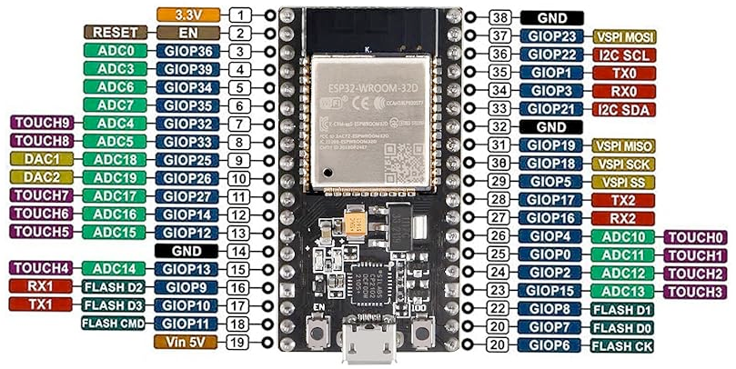
Universal 38-Pin Layout (NodeMCU-32S Style)
This pinout matches most 38-pin ESP32 development boards, including NodeMCU-32S and wider ESP32 DevKit clones.
⚠️ Critical Boot Pins (Strapping Pins):
- GPIO0 - Boot mode: HIGH = normal boot, LOW = download/flash mode
- GPIO2 - Must be LOW or floating during boot (has onboard LED)
- GPIO12 - Flash voltage: LOW = 3.3V (default), HIGH = 1.8V
- GPIO15 - Debug output: LOW = normal (HIGH can cause boot failure)
🔌 Power
- VIN: 5V input (powers regulator)
- USB: 5V Micro-USB
- 3V3 Out: ~600mA max
- GPIO: 40mA/pin max
📡 Serial
- UART0: TX=GPIO1, RX=GPIO3
USB programming - UART1: TX=GPIO10, RX=GPIO9
⚠️ Flash pins - avoid - UART2: TX=GPIO17, RX=GPIO16
Available for sensors
🔧 I2C & SPI
- I2C: SDA=GPIO21, SCL=GPIO22
Software configurable - VSPI: MOSI=23, MISO=19, CLK=18, CS=5
- HSPI: MOSI=13, MISO=12, CLK=14, CS=15
🔧 Analog & Touch Capabilities
Use these when WiFi is active
Not reliable with WiFi
8-bit digital-to-analog
No external components needed
🚫 Do NOT Use These Pins:
- GPIO6-11: Connected to internal SPI flash - will cause boot failure
- These pins are exposed on 38-pin boards but should never be used in your projects
💡 Pro Tips:
- Always use
ADC1channels (GPIO32-39) if WiFi is active - Never use GPIO6-11 - they're connected to flash memory
- GPIO34-39 are input-only (no internal pull-up/down resistors)
- Use external pull-up resistors on I2C lines (4.7kΩ typical)
- Most 38-pin boards have an onboard LED on GPIO2
- VIN pin allows powering the board from external 5V without USB
Safe Pins to Use
These pins are safe for general GPIO usage without boot or system conflicts
Why Are These Pins Safe?
Pins to Avoid or Use with Caution
Reserved for critical functions. Misuse may cause boot failures, programming issues, or system conflicts.
Boot behavior & flash voltage
Low-level debugging interface
USB Serial/JTAG communication
Memory & PSRAM connections
Debugging & firmware uploads
| PIN | Label | Why Avoid | Type |
|---|---|---|---|
| IO36 | GPIO36 (SENSOR_VP) | Cannot be used as output; only suitable for input (e.g., analog read). | 🪛 Other |
| IO39 | GPIO39 (SENSOR_VN) | Cannot be used as output; only suitable for input. | 🪛 Other |
| IO34 | GPIO34 | Cannot be used as output (no drive capability); only suitable for analog/digital input. | 🪛 Other |
| IO35 | GPIO35 | Cannot be used as output; only suitable for input. | 🪛 Other |
| IO14 | MTMS (GPIO14) | Used for JTAG debugging (TMS); driving it as GPIO may interfere with JTAG or produce spurious signals at boot. | 🪛 Other |
| IO12 | MTDI (GPIO12) | Keep LOW during boot (internal PD); pulling HIGH at reset selects 1.8V flash mode, causing flash brownout if 3.3V flash is used. | 🛠️ Strapping |
| IO13 | MTCK (GPIO13) | Used for JTAG debugging (TCK); avoid using as GPIO if JTAG is needed. | 🪛 Other |
| IO9 | GPIO9 (Flash SD2) | Used by internal flash/PSRAM; typically not exposed on modules, avoid using as GPIO. | ⚡ Flash |
| IO10 | GPIO10 (Flash SD3) | Used by internal flash/PSRAM; typically not exposed on modules, avoid using as GPIO. | ⚡ Flash |
| IO11 | GPIO11 (Flash CMD) | Used by internal flash (chip select/command); not available for general use. | ⚡ Flash |
| IO6 | GPIO6 (Flash SCK) | Used for internal flash/PSRAM communication; not available for general GPIO. | ⚡ Flash |
| IO7 | GPIO7 (Flash SD0) | Used for internal flash/PSRAM data; not available for general GPIO. | ⚡ Flash |
| IO8 | GPIO8 (Flash SD1) | Used for internal flash/PSRAM data; not available for general GPIO. | ⚡ Flash |
| IO15 | MTDO (GPIO15) | Keep HIGH during boot (internal PU); if LOW on reset, bootloader log is silenced and boot mode may change. | 🛠️ Strapping |
| IO2 | GPIO2 | If driven HIGH on reset (while IO0 is LOW), selects an unsupported SDIO boot mode, causing boot failure. | 🛠️ Strapping |
| IO0 | GPIO0 | Must be HIGH during boot for normal startup; if held LOW on reset, forces flash programming mode. | 🛠️ Strapping |
| IO4 | GPIO4 | Sampled at reset for boot config; should not be driven at boot (affects boot mode timing). | 🛠️ Strapping |
| IO16 | GPIO16 | Connected to internal PSRAM on PSRAM-enabled modules; not usable as GPIO on those modules. | ⚡ Flash |
| IO17 | GPIO17 | Connected to internal PSRAM on PSRAM-enabled modules; not usable as GPIO on those modules. | ⚡ Flash |
| IO5 | GPIO5 | Must be HIGH during boot; if pulled LOW at reset, alters SDIO slave timing and may prevent normal boot. | 🛠️ Strapping |
Useful Links
Datasheets and resources for ESP32 38-Pin DevKit (Generic Clone)
ESP32 38-Pin DevKit (Generic Clone) Custom Pin Mapping
Pin configuration and GPIO mapping for ESP32 38-Pin DevKit (Generic Clone)
| Pin | Function | ESP Pin | I/O Type | Description |
|---|---|---|---|---|
| 1 | 3V3 | 3.3V | POWER OUTPUT | 3.3V regulated output (~600mA max) |
| 2 | EN | EN | INPUT | Enable/Reset pin (active LOW) |
| 3 | IO36 | VP / SVP | INPUT ONLY | ADC1_CH0, input only, no pull resistors |
| 4 | IO39 | VN / SVN | INPUT ONLY | ADC1_CH3, input only, no pull resistors |
| 5 | IO34 | INPUT ONLY | INPUT ONLY | ADC1_CH6, input only |
| 6 | IO35 | INPUT ONLY | INPUT ONLY | ADC1_CH7, input only |
| 7 | IO32 | GPIO32 | BIDIRECTIONAL | ADC1_CH4, Touch9 |
| 8 | IO33 | GPIO33 | BIDIRECTIONAL | ADC1_CH5, Touch8 |
| 9 | IO25 | GPIO25 | BIDIRECTIONAL | DAC1, ADC2_CH8 |
| 10 | IO26 | GPIO26 | BIDIRECTIONAL | DAC2, ADC2_CH9 |
| 11 | IO27 | GPIO27 | BIDIRECTIONAL | ADC2_CH7, Touch7 |
| 12 | IO14 | GPIO14 | BIDIRECTIONAL | ADC2_CH6, Touch6, HSPI_CLK |
| 13 | IO12 | GPIO12 | BIDIRECTIONAL | ADC2_CH5, Touch5, HSPI_MISO, ⚠️ Strapping pin |
| 14 | GND | GND | GROUND | Ground connection |
| 15 | IO13 | GPIO13 | BIDIRECTIONAL | ADC2_CH4, Touch4, HSPI_MOSI |
| 16 | IO9 | SD2 | SPECIAL | ⚠️ Flash pin - Do not use |
| 17 | IO10 | SD3 | SPECIAL | ⚠️ Flash pin - Do not use |
| 18 | IO11 | CMD | SPECIAL | ⚠️ Flash pin - Do not use |
| 19 | VIN | 5V IN | POWER INPUT | 5V input to onboard regulator |
| 20 | GND | GND | GROUND | Ground connection |
| 21 | IO6 | CLK | SPECIAL | ⚠️ Flash pin - Do not use |
| 22 | IO7 | SD0 | SPECIAL | ⚠️ Flash pin - Do not use |
| 23 | IO8 | SD1 | SPECIAL | ⚠️ Flash pin - Do not use |
| 24 | IO15 | GPIO15 | BIDIRECTIONAL | ADC2_CH3, Touch3, HSPI_CS, ⚠️ Strapping pin |
| 25 | IO2 | GPIO2 | BIDIRECTIONAL | ADC2_CH2, Touch2, LED, ⚠️ Strapping pin |
| 26 | IO0 | GPIO0 | BIDIRECTIONAL | ADC2_CH1, Touch1, ⚠️ Boot button (strapping pin) |
| 27 | IO4 | GPIO4 | BIDIRECTIONAL | ADC2_CH0, Touch0 |
| 28 | IO16 | RX2 | BIDIRECTIONAL | UART2 RX |
| 29 | IO17 | TX2 | BIDIRECTIONAL | UART2 TX |
| 30 | IO5 | GPIO5 | BIDIRECTIONAL | VSPI_CS |
| 31 | IO18 | GPIO18 | BIDIRECTIONAL | VSPI_CLK |
| 32 | IO19 | GPIO19 | BIDIRECTIONAL | VSPI_MISO |
| 33 | GND | GND | GROUND | Ground connection |
| 34 | IO21 | GPIO21 | BIDIRECTIONAL | I2C_SDA (default) |
| 35 | RX0 | GPIO3 | BIDIRECTIONAL | UART0 RX (USB serial) |
| 36 | TX0 | GPIO1 | BIDIRECTIONAL | UART0 TX (USB serial) |
| 37 | IO22 | GPIO22 | BIDIRECTIONAL | I2C_SCL (default) |
| 38 | IO23 | GPIO23 | BIDIRECTIONAL | VSPI_MOSI |
Default Tools & Configuration
Build and upload settings for ESP32 38-Pin DevKit (Generic Clone)
| Setting | Value |
|---|---|
| Bootloader tool | esptool_py |
| Uploader tool | esptool_py |
| Network uploader tool | esp_ota |
| Bootloader address | 0x1000 |
| Flash mode | dio |
| Boot mode | dio |
| Maximum upload size | 1280 KB (1310720 bytes) |
| Maximum data size | 320 KB (327680 bytes) |
The ESP32 38-Pin DevKit (Generic Clone) uses esptool_py for uploads , esp_ota for OTA updates, and esptool_py bootloader at 0x1000.
Flash mode: dio | Boot mode: dio
Max sketch size: 1280 KB | Max data size: 320 KB
Similar Boards
Other development boards with ESP32 microcontroller

pyWiFi-ESP32 Development Board Kit
pyWiFi-ESP32 Development Board Kit development board is based on esp32 microcontroller and uses xtensa...

Trueverit ESP32 Universal IoT Driver
Trueverit ESP32 Universal IoT Driver development board is based on esp32 microcontroller and uses xtensa...

Turta IoT Node
Turta IoT Node development board is based on esp32 microcontroller and uses xtensa architecture.