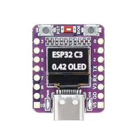
ESP32-C3 OLED 0.42" Display Development Board
Code name: ESP32C3_DEV
ESP32-C3 OLED 0.42" Display development board is based on esp32c3 microcontroller and uses riscv32 architecture. This board has a maximum CPU frequency of 160 MHz and a flash size of 4MB.
About ESP32-C3 OLED 0.42" Display
The ESP32-C3 OLED 0.42" is a compact development board featuring the ESP32-C3 RISC-V microcontroller with integrated Wi-Fi 802.11 b/g/n and Bluetooth 5 (LE) connectivity. 📶
Powered by a 32-bit RISC-V single-core processor running at up to 160 MHz, with 4MB flash memory and 400KB SRAM, it's perfect for IoT applications and embedded projects. ⚡
The board features a built-in 0.42" OLED display with 72x40 resolution connected via I2C, ideal for displaying sensor data, status information, or user interfaces. It offers 13 GPIO pins with support for ADC (6 channels, 12-bit), PWM, and various communication interfaces including UART, SPI, I2C, and I2S. 🔌
Operating at 3.3V with Micro-USB interface for programming and power. Ultra-compact design makes it suitable for wearable and space-constrained applications. 🔋
Where to Buy ESP32-C3 OLED 0.42" Display

Starting from
$8.99


Prices are subject to change. We earn from qualifying purchases as an Amazon Associate.
ESP32-C3 OLED 0.42" Display Technical Specifications
🖥️ Display
🔌 USB
🛰️ Connectivity
🧠 Microcontroller
✨ Features
- OLED Screen
- 13 digital IO pins
- 22 external interrupt pins
- 6 analog input pins
- 11 PWM pins
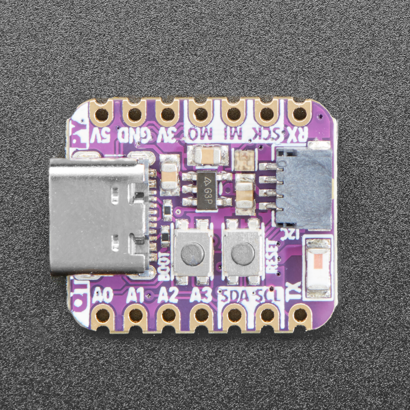
ESP32-C3 OLED 0.42" Display Pinout
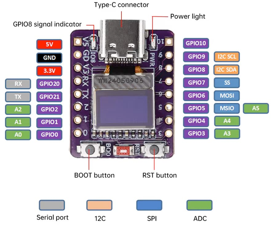
The ESP32-C3 OLED 0.42" pinout provides 13 GPIO pins in a compact layout. Power pins include 3V3 for 3.3V supply and GND for ground connection.
The integrated 0.42" OLED display uses I2C communication (typically GPIO 8 for SDA and GPIO 9 for SCL). GPIO pins support digital I/O, ADC, PWM, and multiple protocols.
Communication pins include RX and TX for UART, while other GPIOs can be configured for SPI, I2C, PWM, and more. ADC channels provide 12-bit analog input.
✅ Safe Pins to Use
For general GPIO usage, these are the safest and most flexible choices:
Why Are These Pins Safe?
- Not involved in bootstrapping → No impact on device boot mode or system startup
- Not linked to flash memory or PSRAM → Won't interfere with storage or memory access
- Not dedicated to USB or JTAG → Free for general use without affecting debugging
- No special hardware connections → Freely assignable without internal conflicts
⚠️ Pins to Avoid or Use with Caution
Some pins are reserved for critical functions like bootstrapping, JTAG debugging, USB communication, and flash memory operations. Misusing these pins may lead to boot failures, programming issues, USB conflicts, or disruptions in flash storage.
Critical Pin Categories:
- 🛠️ Strapping Pins: Control boot behavior and flash voltage selection
- 🔗 JTAG Debugging Pins: Required for low-level debugging
- 🔌 USB Communication Pins: Used for USB Serial/JTAG communication
- ⚡ Flash Memory & SPI Pins: Connected to SPI flash memory and PSRAM
- 📡 UART Serial Communication Pins: Used for debugging and firmware uploads
| PIN | Label | Reason | Function |
|---|---|---|---|
| IO2 | GPIO2 | Must be held high during boot (if low on reset, normal flash boot may fail) | 🛠️ Strapping |
| IO4 | MTMS | Used during boot; JTAG TMS for debugging; acts as Quad-SPI flash IO (hold data line) in internal-flash variants | 🔗 JTAG |
| IO5 | MTDI | Used during boot; JTAG TDI for debugging; acts as Quad-SPI flash IO (write-protect data line) in internal-flash variants | 🔗 JTAG |
| IO6 | MTCK | Used during boot; JTAG TCK for debugging; provides flash clock in internal-flash variants | 🔗 JTAG |
| IO7 | MTDO | Used during boot; JTAG TDO for debugging; acts as Quad-SPI flash IO (data line) in internal-flash variants | 🔗 JTAG |
ESP32-C3 OLED 0.42" Features
📺 Built-in Display
- 0.42" OLED Screen: 72x40 resolution with high contrast
- I2C Interface: Connected to GPIO 8 (SDA) and GPIO 9 (SCL)
- Driver: SSD1306 controller for easy integration
⚙️ Technical Specifications
Based on ESP32-C3 RISC-V processor with 13 GPIO pins. Perfect for projects requiring visual feedback in ultra-compact form factors.
💡 Perfect For
Ideal for wearable devices, smart sensors, mini IoT projects, and applications where a tiny display is essential without external components.
ESP32-C3 OLED 0.42" Display Useful Links
🔗 Datasheet
https://github.com/zhuhai-esp/ESP32-C3-ABrobot-OLED/blob/main/Document/SPEC%20N042-7240TSWEG01-H16%20VER%20A.pdf
🔗 ESP32C3 Datasheet
https://www.espressif.com/sites/default/files/documentation/esp32-c3_datasheet_en.pdf
🔗 ESP32-C3 0.42 OLED Schematic
https://github.com/zhuhai-esp/ESP32-C3-ABrobot-OLED/blob/main/Document/ESP32C3%20OLED%E5%8E%9F%E7%90%86%E5%9B%BE.pdf
ESP32-C3 OLED 0.42" Display Pin Mappings
This development board provides 13 digital IO pins, out of which 22 can be used as external interrupt pins , 6 as analog input pins and 11 pins have Pulse-Width Modulation (PWM) .
| Pin | Function | ESP Pin | Input/Output | Description |
|---|---|---|---|---|
| 1 | IO08 | GPIO8 | BIDIRECTIONAL | I2C Data Line for OLED |
| 2 | IO09 | GPIO9 | BIDIRECTIONAL | I2C Clock Line for OLED |
| 3 | IO0 | GPIO0 | BIDIRECTIONAL | GPIO0, ADC0 |
| 4 | IO1 | GPIO1 | BIDIRECTIONAL | GPIO1, ADC1 |
| 5 | IO2 | GPIO2 | BIDIRECTIONAL | GPIO2, ADC2 |
| 6 | IO3 | GPIO3 | BIDIRECTIONAL | GPIO3, ADC3 |
| 7 | IO4 | GPIO4 | BIDIRECTIONAL | GPIO4, ADC4, SCK |
| 8 | IO5 | GPIO5 | BIDIRECTIONAL | GPIO5, ADC5, MISO |
| 9 | IO6 | GPIO6 | BIDIRECTIONAL | GPIO6, MOSI |
| 10 | IO7 | GPIO7 | BIDIRECTIONAL | GPIO7, SS |
| 11 | IO10 | GPIO10 | BIDIRECTIONAL | GPIO10, RX |
| 12 | IO20 | GPIO20 | BIDIRECTIONAL | GPIO20, RX |
| 13 | IO21 | GPIO21 | BIDIRECTIONAL | GPIO21, TX |
ESP32-C3 OLED 0.42" Display Pins Mapping Arduino IDE
Below you can find the ESP32-C3 OLED 0.42" Display pinout. This development board provides 13 digital IO pins, out of which 22 can be used as external interrupt pins, 6 as analog input pins and 11 pins have Pulse-Width Modulation (PWM).
| Pin | Analog | Touch | PWM | Other |
|---|---|---|---|---|
| 0 | A0 | |||
| 1 | A1 | |||
| 2 | A2 | |||
| 3 | A3 | |||
| 4 | A4 | SCK | ||
| 5 | A5 | MISO | ||
| 6 | MOSI | |||
| 7 | SS | |||
| 8 | SDA | |||
| 9 | SCL | |||
| 10 | RX | |||
| 20 | RX | |||
| 21 | TX |
Default Tools for ESP32-C3 OLED 0.42" Display
| Bootloader tool | esptool_py |
| Uploader tool | esptool_py |
| Network uploader tool | esp_ota |
| Bootloader address | 0x0 |
| Flash mode | qio |
| Boot mode | qio |
| Maximum upload size | 1280 Kb (1310720 B) |
| Maximum data size | 320 Kb (327680 B) |
The ESP32-C3 OLED 0.42" Display development board by default uses esptool_py uploader tool, esp_ota network uploader tool for Over-the-air (OTA) uploads and esptool_py bootloader tool. The bootloader starts at address "0x0". Flash mode and boot mode for ESP32-C3 OLED 0.42" Display development board by default is qio and qio respectively.