
ESP32-C3 OLED 0.42" Display
ESP32-C3 development board with integrated 0.42" OLED display and RISC-V processor for compact IoT projects.

Pinout
13 pins · 2.54 mm pitch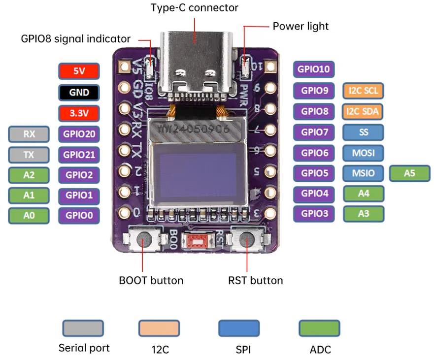
| Pin | GPIO | Labels | Status | Capabilities | Notes |
|---|---|---|---|---|---|
| 1 | 8 | IO08GPIO8 | strapping | i2c | I2C Data Line for OLED |
| 2 | 9 | IO09GPIO9 | strapping | i2c | I2C Clock Line for OLED |
| 3 | 0 | IO0GPIO0 | safe | adc | GPIO0, ADC0 |
| 4 | 1 | IO1GPIO1 | safe | adc | GPIO1, ADC1 |
| 5 | 2 | IO2GPIO2 | strapping | adc | GPIO2, ADC2 |
| 6 | 3 | IO3GPIO3 | safe | adc | GPIO3, ADC3 |
| 7 | 4 | IO4GPIO4 | strapping | adc | GPIO4, ADC4, SCK |
| 8 | 5 | IO5GPIO5 | strapping | adc | GPIO5, ADC5, MISO |
| 9 | 6 | IO6GPIO6 | strapping | - | GPIO6, MOSI |
| 10 | 7 | IO7GPIO7 | strapping | - | GPIO7, SS |
| 11 | 10 | IO10GPIO10 | safe | - | GPIO10, RX |
| 12 | 20 | IO20GPIO20 | uart | - | GPIO20, RX |
| 13 | 21 | IO21GPIO21 | uart | - | GPIO21, TX |
Start with these
4 pins with no boot or system involvementFreely assignable - no strapping, flash, USB or JTAG duties. Ideal first picks for buttons, sensors and LEDs.
Fine - with a little care
sampled at boot or shared with debug/serial| Pin | Label | What to know | Role |
|---|---|---|---|
| IO08 | GPIO8 | Must be held high during reset (if low, UART flashing/boot may not work) | Strapping |
| IO09 | GPIO9 | Controls boot mode on reset (HIGH for normal flash boot, LOW enters serial download mode) | Strapping |
| IO2 | GPIO2 | Must be held high during boot (if low on reset, normal flash boot may fail) | Strapping |
| IO4 | MTMS | Used during boot; JTAG TMS for debugging; acts as Quad-SPI flash IO (hold data line) in internal-flash variants | JTAG |
| IO5 | MTDI | Used during boot; JTAG TDI for debugging; acts as Quad-SPI flash IO (write-protect data line) in internal-flash variants | JTAG |
| IO6 | MTCK | Used during boot; JTAG TCK for debugging; provides flash clock in internal-flash variants | JTAG |
| IO7 | MTDO | Used during boot; JTAG TDO for debugging; acts as Quad-SPI flash IO (data line) in internal-flash variants | JTAG |
| IO20 | U0RXD | Used as UART0 receive (console/bootloader); repurposing may disable serial programming and debug logs | UART |
| IO21 | U0TXD | Used as UART0 transmit (console/bootloader); repurposing may disable serial console output and printing | UART |
Pinout notes The ESP32-C3 OLED 0.42" Display pinout brings out 13 GPIO pins at a 2.54 mm pitch - every one of them usable in your project. On the analog side there are 6…
The ESP32-C3 OLED 0.42" Display pinout brings out 13 GPIO pins at a 2.54 mm pitch - every one of them usable in your project.
On the analog side there are 6 ADC-capable pins for sensors and battery monitoring.
If you want zero surprises, IO0, IO1, IO3 and IO10 are free of any such role - the safest first picks. 9 of the exposed pins carry boot-time or system duties on the ESP32-C3 (IO08, IO09, IO2 and 6 more).
Getting started
flash your first firmware in ~2 minutesBoard: Esp32c3 Dev
Flash Size: 4MB · QIO
Upload Speed: 921600
// blink
pinMode(0, OUTPUT);
digitalWrite(0, LOW); // on (often inverted)[env:esp32-c3-oled-042]
platform = espressif32
board = esp32-c3-devkitm-1
framework = arduino
monitor_speed = 115200
upload_speed = 921600esp32:
board: esp32-c3-devkitm-1
variant: esp32c3
framework:
type: esp-idf
# blink - GPIO0
output:
- platform: gpio
pin: 0
id: led_out
light:
- platform: binary
name: "LED"
output: led_outesptool.py --chip esp32c3 --port /dev/ttyACM0 \
write_flash 0x0 firmware.binGood to know
board-specific quirks worth 60 seconds
ESP32-C3 OLED 0.42" Features Built-in Display 0.42" OLED Screen: 72x40 resolution with high contrast I2C Interface: Connected to GPIO 8 (SDA) and GPIO 9 (SCL) Driver: SSD1306 controller for easy integration Technical Specifications Based on ESP32-C3 RISC-V processor with 13 GPIO pins. Perfect for projects requiring visual feedback in ultra-compact form factors. Perfect For Ideal for wearable devices, smart…
ESP32-C3 OLED 0.42" Features
Built-in Display
- 0.42" OLED Screen: 72x40 resolution with high contrast
- I2C Interface: Connected to GPIO 8 (SDA) and GPIO 9 (SCL)
- Driver: SSD1306 controller for easy integration
Technical Specifications
Based on ESP32-C3 RISC-V processor with 13 GPIO pins. Perfect for projects requiring visual feedback in ultra-compact form factors.
Perfect For
Ideal for wearable devices, smart sensors, mini IoT projects, and applications where a tiny display is essential without external components.
Specifications
ESP32-C3 · 24.8 × 20.5 mmAbout this board
At its core is the ESP32-C3 - a single-core RISC-V and the budget low-power pick.
Expect to pay about $8.99 - in line with other ESP32-C3 boards.
Onboard you'll find an OLED 0.42" 72x40 display and Reset/Boot buttons.
The ESP32-C3 OLED 0.42" is a compact development board featuring the ESP32-C3 RISC-V microcontroller with integrated Wi-Fi 802.11 b/g/n and Bluetooth 5 (LE) connectivity.
Powered by a 32-bit RISC-V single-core processor running at up to 160 MHz, with 4MB flash memory and 400KB SRAM, it's perfect for IoT applications and embedded projects.
The board features a built-in 0.42" OLED display with 72x40 resolution connected via I2C, ideal for displaying sensor data, status information, or user interfaces. It offers 13 GPIO pins with support for ADC (6 channels, 12-bit), PWM, and various communication interfaces including UART, SPI, I2C, and I2S.
Operating at 3.3V with Micro-USB interface for programming and power. Ultra-compact design makes it suitable for wearable and space-constrained applications.
- OLED Screen
Where to buy
prices are typical street prices
Resources
Similar boards


