
LOLIN S2 Mini is a development board based on the ESP32S2 microcontroller using XTENSA architecture.
This board features a maximum CPU frequency of 240 MHz and 4MB flash memory.
About LOLIN S2 Mini
Compact ESP32-S2 board by Wemos with USB-C and LiPo charging - perfect for space-saving embedded builds.
Where to Buy LOLIN S2 Mini

Starting from
5$ per unit


Prices are subject to change. We earn from qualifying purchases as an Amazon Associate.
Technical Specifications
Complete technical specification details for LOLIN S2 Mini
Connectivity
Microcontroller
✨ Features & Pins
Quick Setup
Copy-paste configs for LOLIN S2 Mini - auto‑generated from this board's exact hardware specs.
In Arduino IDE 2 select Lolin S2 Mini from the esp32 by Espressif package. In PlatformIO use board = esp32-s2-saola-1. ESP32S2 · 240 MHz · 4MB · DIO.
In Arduino IDE 2, open Boards Manager, search "esp32" by Espressif and install it. Then go to Tools → Board and select "Lolin S2 Mini" for the LOLIN S2 Mini.
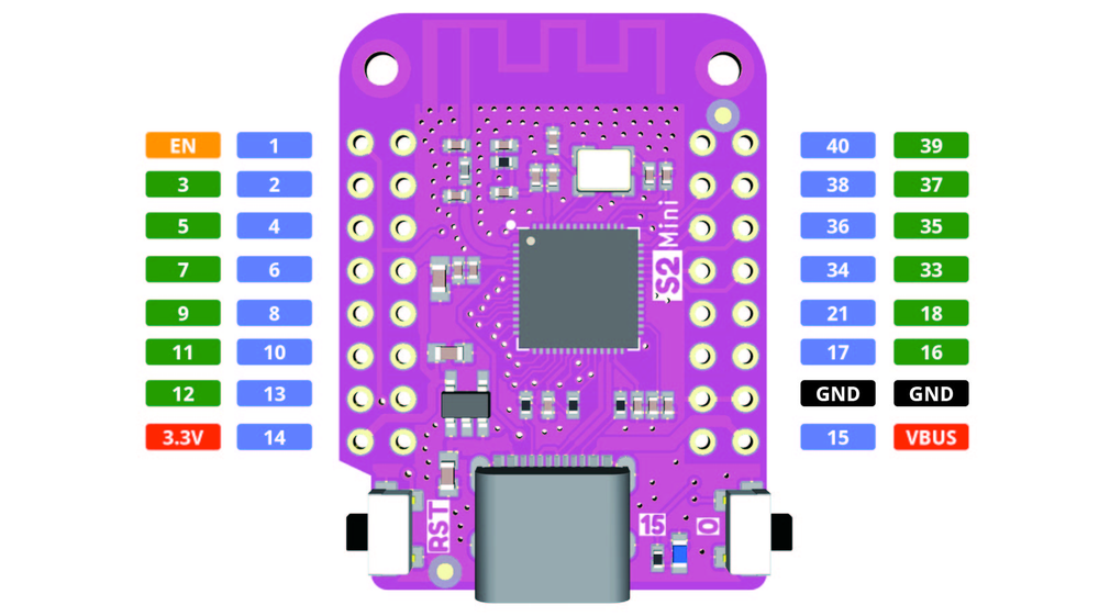
LOLIN S2 Mini Pinout Diagram
Complete pin reference for LOLIN S2 Mini
Safe Pins to Use
These pins are safe for general GPIO usage without boot or system conflicts
Why Are These Pins Safe?
Pins to Avoid or Use with Caution
Reserved for critical functions. Misuse may cause boot failures, programming issues, or system conflicts.
Boot behavior & flash voltage
Low-level debugging interface
USB Serial/JTAG communication
Memory & PSRAM connections
Debugging & firmware uploads
| PIN | Label | Why Avoid | Type |
|---|---|---|---|
| IO9 | FSPIHD | Typically used as flash/PSRAM IO line in certain configurations; avoid using as GPIO if flash or PSRAM is present. | ⚡ Flash |
| IO10 | FSPICS0 | Often used as flash chip select in some designs; not available for GPIO when controlling flash. | ⚡ Flash |
| IO11 | FSPID | Used for flash data transfer in certain configurations; should be avoided for general use if flash is connected. | ⚡ Flash |
| IO12 | FSPICLK | Used as flash clock line in some boards; not free for GPIO if driving flash. | ⚡ Flash |
| IO13 | FSPIQ | Used for flash data output in certain configurations; avoid using as GPIO if connected to flash. | ⚡ Flash |
| IO14 | FSPIWP | Used as flash write-protect/data line on some modules; not recommended for other usage. | ⚡ Flash |
| IO15 | XTAL_32K_P | If an external 32 kHz crystal is used for RTC, this pin is dedicated to the crystal and cannot be used as GPIO. | 🪛 Other |
| IO16 | XTAL_32K_N | If using an external 32 kHz crystal, this pin is connected to the crystal and should not be used as general I/O. | 🪛 Other |
| IO33 | SPIHD | Connected to SPI flash (hold/data line); not available for general-purpose use. | ⚡ Flash |
| IO34 | SPIWP | Connected to SPI flash (write-protect/data line); not recommended for other use. | ⚡ Flash |
| IO35 | FSPID | Used by internal flash/PSRAM on some ESP32-S2 variants; avoid using as GPIO to prevent conflicts. | ⚡ Flash |
| IO36 | FSPICLK | May be connected to internal flash or used for high-speed SPI; not intended for general GPIO use. | ⚡ Flash |
| IO37 | FSPIQ | Used for internal flash/PSRAM data in some models; should not be repurposed for GPIO. | ⚡ Flash |
| IO38 | FSPIWP | Reserved for flash/PSRAM in ESP32-S2 modules with internal memory; not recommended for general I/O. | ⚡ Flash |
| IO39 | MTCK | Used for JTAG debugging interface; using this pin for other purposes will disable JTAG clock input. | 🪛 Other |
| IO40 | MTDO | Part of JTAG interface (TDO); should be avoided as GPIO if JTAG debugging is needed. | 🪛 Other |
LOLIN S2 Mini Custom Pin Mapping
Pin configuration and GPIO mapping for LOLIN S2 Mini
| Pin | Function | ESP Pin | I/O Type | Description |
|---|---|---|---|---|
| 1 | 5V | 5V | POWER INPUT | 5V power input for the board |
| 2 | GND | GND | POWER GROUNT | Ground connection |
| 3 | 3V3 | 3.3V | POWER OUTPUT | 3.3V power output |
| 5 | IO1 | GPIO1 | BIDIRECTIONAL | GPIO |
| 6 | IO2 | GPIO2 | BIDIRECTIONAL | GPIO, ADC |
| 7 | IO3 | GPIO3 | BIDIRECTIONAL | GPIO |
| 8 | IO4 | GPIO4 | BIDIRECTIONAL | GPIO, ADC |
| 9 | IO5 | GPIO5 | BIDIRECTIONAL | GPIO |
| 10 | IO6 | GPIO5 | BIDIRECTIONAL | GPIO |
| 11 | IO7 | GPIO5 | BIDIRECTIONAL | GPIO |
| 12 | IO8 | GPIO5 | BIDIRECTIONAL | GPIO |
| 13 | IO9 | GPIO5 | BIDIRECTIONAL | GPIO |
| 14 | IO10 | GPIO5 | BIDIRECTIONAL | GPIO |
| 15 | IO11 | GPIO5 | BIDIRECTIONAL | GPIO |
| 16 | IO12 | GPIO12 | BIDIRECTIONAL | GPIO, ADC |
| 17 | IO13 | GPIO13 | BIDIRECTIONAL | GPIO, ADC |
| 18 | IO14 | GPIO14 | BIDIRECTIONAL | GPIO, ADC |
| 19 | IO15 | GPIO15 | BIDIRECTIONAL | GPIO, ADC |
| 20 | IO16 | GPIO16 | BIDIRECTIONAL | GPIO |
| 21 | IO17 | GPIO17 | BIDIRECTIONAL | GPIO |
| 22 | IO18 | GPIO18 | BIDIRECTIONAL | GPIO |
| 23 | IO21 | GPIO21 | BIDIRECTIONAL | GPIO |
| 24 | IO33 | GPIO33 | BIDIRECTIONAL | GPIO, ADC |
| 25 | IO34 | GPIO34 | INPUT | GPIO, ADC |
| 26 | IO35 | GPIO35 | INPUT | GPIO, ADC |
| 27 | IO36 | GPIO36 | INPUT | GPIO, ADC |
| 28 | IO37 | GPIO37 | INPUT | GPIO, ADC |
| 29 | IO38 | GPIO38 | INPUT | GPIO, ADC |
| 30 | IO39 | GPIO39 | INPUT | GPIO, ADC |
| 31 | IO40 | GPIO40 | INPUT | GPIO, ADC |
Pin Mappings
Complete pinout and GPIO mapping for LOLIN S2 Mini
| Pin | Analog | Touch | PWM | Other |
|---|---|---|---|---|
| 1 | A0 | T1 | PWM | |
| 2 | A1 | T2 | PWM | |
| 3 | A2 | T3 | PWM | |
| 4 | A3 | T4 | PWM | |
| 5 | A4 | T5 | PWM | |
| 6 | A5 | T6 | PWM | |
| 7 | A6 | T7 | PWM | SCK |
| 8 | A7 | T8 | PWM | |
| 9 | A8 | T9 | PWM | MISO |
| 10 | A9 | T10 | PWM | |
| 11 | A10 | T11 | PWM | MOSI |
| 12 | A11 | T12 | PWM | SS |
| 13 | A12 | T13 | PWM | |
| 14 | A13 | T14 | PWM | |
| 15 | A14 | PWM | LED_BUILTIN | |
| 16 | A15 | PWM | ||
| 17 | A16 | PWM | DAC1 | |
| 18 | A17 | PWM | DAC2 | |
| 19 | A18 | PWM | ||
| 20 | A19 | PWM | ||
| 33 | PWM | SDA | ||
| 35 | PWM | SCL | ||
| 37 | PWM | RX | ||
| 39 | PWM | TX | ||
| 0x00000000 | USB_FW_MSC_SERIAL_NUMBER |
Default Tools & Configuration
Build and upload settings for LOLIN S2 Mini
| Setting | Value |
|---|---|
| Bootloader tool | esptool_py |
| Uploader tool | esptool_py |
| Network uploader tool | esp_ota |
| Bootloader address | 0x1000 |
| Flash mode | dio |
| Boot mode | qio |
| Maximum upload size | 1280 KB (1310720 bytes) |
| Maximum data size | 320 KB (327680 bytes) |
The LOLIN S2 Mini uses esptool_py for uploads , esp_ota for OTA updates, and esptool_py bootloader at 0x1000.
Flash mode: dio | Boot mode: qio
Max sketch size: 1280 KB | Max data size: 320 KB
Similar Boards
Other development boards with ESP32S2 microcontroller

LOLIN D32 PRO
LOLIN D32 PRO development board is based on esp32 microcontroller and uses xtensa architecture.

WEMOS D1 MINI ESP32
WEMOS D1 MINI ESP32 development board is based on esp32 microcontroller and uses xtensa architecture.

WEMOS LOLIN32 Lite
WEMOS LOLIN32 Lite development board is based on esp32 microcontroller and uses xtensa architecture.