
Waveshare ESP32-S3 Touch LCD 7B
7" 1024×600 IPS touch HMI panel on an ESP32-S3 N16R8 with CAN, RS-485, microSD, Li-ion charging and dual USB-C ports.

Waveshare ESP32-S3 Touch LCD 7B Pinout
13 pins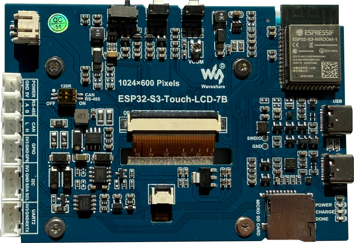
| Pin | GPIO | Labels | Status | Capabilities | Notes |
|---|---|---|---|---|---|
| 1 | - | 5V | power | - | 5V input on the POWER header (alternative to USB-C) |
| 2 | - | 3V3 | power | - | 3.3V rail on the I2C, UART2 and GPIO headers |
| 3 | - | GND | ground | - | Ground, present on every JST header |
| 4 | - | BAT | power | - | 3.7V Li-ion via PH2.0 connector - CS8501 charge management |
| 5 | 6 | GP6 | safe | adc · touch | The only fully free GPIO, on the 3-pin GPIO header |
| 6 | 8 | SDA | safe | i2c | I2C header - bus shared with the GT911 touch and CH32V003 expander |
| 7 | 9 | SCL | strapping | i2c | I2C header - bus shared with the GT911 touch and CH32V003 expander |
| 8 | 43 | TXU0TXD | uart | uart | UART2 header - slide switch selects it or the USB-UART port |
| 9 | 44 | RXU0RXD | uart | uart | UART2 header - slide switch selects it or the USB-UART port |
| 10 | - | A | safe | - | RS-485 bus A - SP3485 transceiver on GPIO15 (TX) / GPIO16 (RX) |
| 11 | - | B | safe | - | RS-485 bus B - SP3485 transceiver on GPIO15 (TX) / GPIO16 (RX) |
| 12 | - | H | safe | - | CAN high - TJA1051 transceiver on GPIO20 (TX) / GPIO19 (RX), shared with USB |
| 13 | - | L | safe | - | CAN low - TJA1051 transceiver on GPIO20 (TX) / GPIO19 (RX), shared with USB |
Start with these
2 pins with no boot or system involvementFreely assignable - no strapping, flash, USB or JTAG duties. Ideal first picks for buttons, sensors and LEDs.
Fine - with a little care
3 pins · 3 things to knowSCLGPIO9 General-purpose SPI2 (FSPI) IO MUX pin - hold/data line (FSPIHD) Other
IO MUX pin of the general-purpose SPI2 (FSPI) bus, not of the in-package flash - that sits on GPIO26-32. The datasheet lists it as a priority-2 pin ("can be freely used without restrictions"), so it is only taken if your board wires flash, an SD card or a display to FSPI.
TXGPIO43 UART0 transmit pin (U0TXD), default serial console TX UART
Used for bootloader output and UART console logs. If repurposed, you will lose the default serial output (and programming via UART0).
RXGPIO44 UART0 receive pin (U0RXD), default serial console RX UART
Used for bootloader input (download mode via serial). If repurposed, you cannot use the default UART0 download mode for programming the chip.
The Waveshare ESP32-S3 Touch LCD 7B breaks out 13 pins in total: 5 GPIO for your project, with 5V, 3V3, GND and BAT handling power.
Peripheral wiring is straightforward: I²C is mapped to SDA on GPIO8 and SCL on GPIO9, while TX/RX on GPIO43 and GPIO44 cover serial logging and flashing.
Beyond plain digital I/O you get 1 ADC-capable pin for sensors and battery monitoring and 1 capacitive-touch inputs.
3 of the exposed pins carry boot-time or system duties on the ESP32-S3 (SCL, TX and RX) - check the guidance above before wiring anything to them. GP6 and SDA are free of any such role - the safest first picks.
Getting started
flash your first firmware in ~2 minutesBoard: ESP32S3 Dev Module USB CDC On Boot: Enabled Flash Size: 16MB (128Mb) Flash Mode: QIO PSRAM: OPI PSRAM Partition Scheme: 16M Flash (3MB APP/9.9MB FATFS) Upload Speed: 921600
// toggle GPIO6 - wire an LED and resistor to it
void setup() {
  pinMode(6, OUTPUT);
}
void loop() {
  digitalWrite(6, HIGH); delay(500);
  digitalWrite(6, LOW);  delay(500);
}[env:waveshare-esp32-s3-touch-lcd-7b]
platform = espressif32
board = esp32-s3-devkitc-1
framework = arduino
monitor_speed = 115200
upload_speed = 921600
board_build.arduino.memory_type = qio_opi
build_flags = -DBOARD_HAS_PSRAMesp32-s3-devkitc-1 - or type it after board =.esp32:
board: esp32-s3-devkitc-1
variant: esp32s3
framework:
type: esp-idf
psram:
mode: octal
speed: 80MHz
# blink - GPIO6
output:
- platform: gpio
pin: 6
id: led_out
light:
- platform: binary
name: "LED"
output: led_outesp32-s3-devkitc-1 (same ids as PlatformIO).esptool.py --chip esp32s3 --port /dev/ttyACM0 \
--baud 921600 write_flash 0x0 firmware.bin--port = your /dev/tty* (macOS/Linux) or COMx (Windows).Good to know
board-specific quirks worth 60 seconds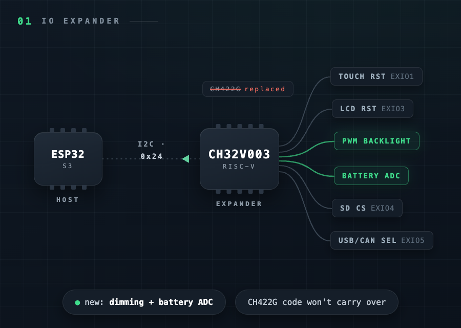
Code and configs written for the older Touch-LCD-7 won't carry over directly: the 7B replaces the CH422G expander with a CH32V003 microcontroller running IO-expander firmware at I2C address 0x24. It drives touch reset, display reset, the SD chip-select and the USB/CAN switch - and it does two things the CH422G couldn't: PWM backlight dimming and battery-voltage readout through its ADC. ESPHome supports it…
Code and configs written for the older Touch-LCD-7 won't carry over directly: the 7B replaces the CH422G expander with a CH32V003 microcontroller running IO-expander firmware at I2C address 0x24. It drives touch reset, display reset, the SD chip-select and the USB/CAN switch - and it does two things the CH422G couldn't: PWM backlight dimming and battery-voltage readout through its ADC.
ESPHome supports it natively since mid-2026 via the waveshare_io_ch32v003 component, so backlight brightness and battery monitoring work without custom code.
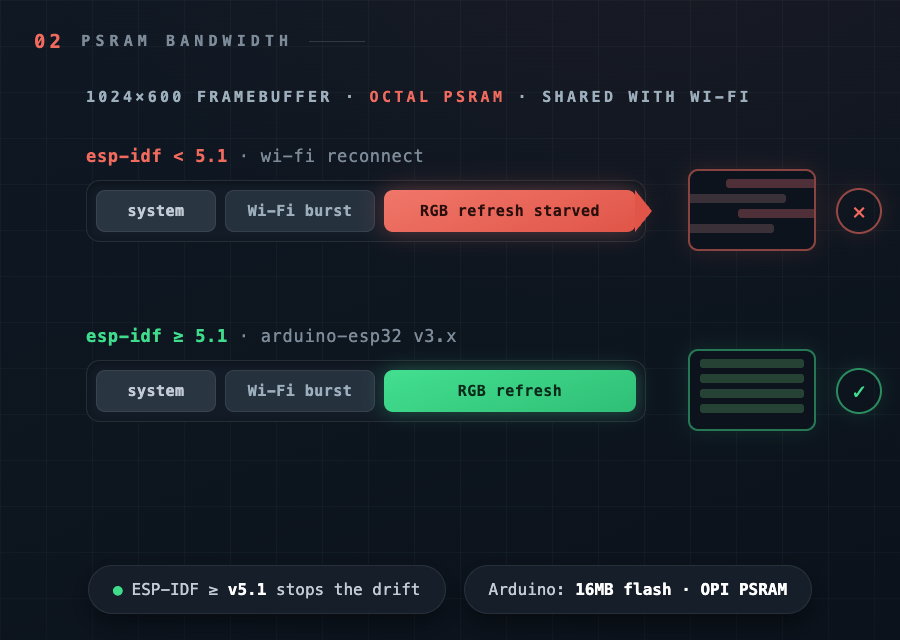
The 1024×600 framebuffer lives in the octal PSRAM, and heavy Wi-Fi activity can starve the panel refresh - it shows up as horizontal drift, flicker, or a screen that comes up shifted by half a page, often right when Wi-Fi reconnects. Waveshare's fix is ESP-IDF v5.1 or later (arduino-esp32 v3.x); lowering the pixel clock helps if it persists. In the Arduino IDE, set Flash Size to 16MB and PSRAM to OPI PSRAM…
The 1024×600 framebuffer lives in the octal PSRAM, and heavy Wi-Fi activity can starve the panel refresh - it shows up as horizontal drift, flicker, or a screen that comes up shifted by half a page, often right when Wi-Fi reconnects. Waveshare's fix is ESP-IDF v5.1 or later (arduino-esp32 v3.x); lowering the pixel clock helps if it persists.
In the Arduino IDE, set Flash Size to 16MB and PSRAM to OPI PSRAM - with the defaults the framebuffer allocation fails and the screen simply stays black.
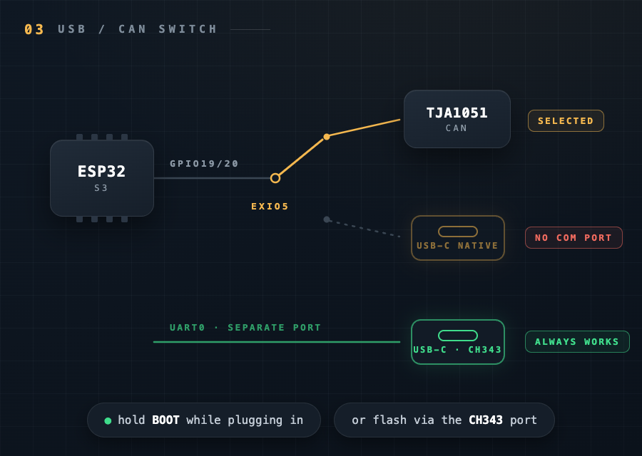
The native USB-C port only enumerates while the onboard analog switch routes GPIO19/20 to USB - if the running firmware has selected CAN, no COM port appears at all. Hold BOOT while plugging in power to force download mode, or flash through the second USB-C port: it goes through the CH343 USB-UART chip and works regardless of the switch position.
Gallery
3 photos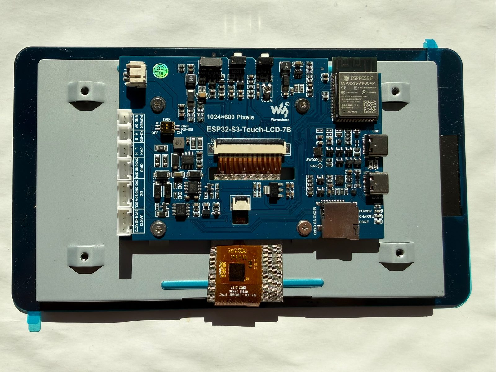
Specifications
ESP32-S3 · 192.96 × 110.76 mm · vs other ESP32 chips →Dimensions
About this board
Inside sits the ESP32-S3 - a dual-core Xtensa with vector extensions suited to AI workloads.
At $38.99 it's on the expensive side for an ESP32-S3 board - most land around $29.
Only 5 GPIO are left for your own hardware - the display and onboard peripherals claim the rest.
Around the module: 8MB (OPI) PSRAM, an IPS LCD 7.0" 1024x600 display with touch, a microSD slot, an RS485 interface (SP3485), a CAN bus interface (TJA1051), battery charging (CS8501) via PH2.0, status LEDs (Power, Charge, Done) and Reset/Boot buttons.
- ESP32-S3-WROOM-1-N16R8 module - 16MB flash + 8MB octal PSRAM
- 5-point capacitive touch on tempered glass, 235 cd/m² brightness
- CH32V003 helper MCU as I2C IO expander (0x24) - touch reset, display reset, SD chip-select, USB/CAN switch, PWM backlight dimming and battery-voltage ADC
- Total thickness ~18.3 mm from screen glass to the top of the terminal blocks
- CAN shares GPIO19/20 with native USB - selectable, not usable simultaneously
- Slide switch routes UART0 (GPIO43/44) to either the USB-UART port or the UART2 header
- Onboard 120Ω termination DIP switch for the CAN and RS-485 buses
- Backlight boost converter (AP3032) with VCOM trimmer for panel tuning
- PCB without touch glass measures 164 × 97 mm
FAQ
7 common questionsCan I use the native USB port and the CAN bus at the same time?›
How do I connect my own sensors when almost every GPIO drives the display?›
Why doesn't my computer detect a COM port on the native USB-C port?›
The screen stays black after flashing from the Arduino IDE - what's wrong?›
Why does the display drift or flicker, especially when Wi-Fi reconnects?›
RS-485 transmits but never receives anything - is my board broken?›
Does it work with ESPHome and Home Assistant?›
Where to buy
prices are typical street pricesResources
Similar boards

