ESP32 DHT11 Temperature and Humidity Sensor
Overview
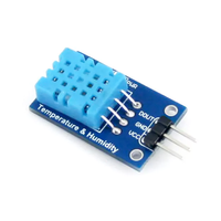
The DHT11 is a low-cost digital sensor for measuring temperature and humidity. It provides calibrated digital outputs and is easy to interface with microcontrollers. With a temperature measurement range of 0-50°C and humidity range of 20-90%, it's suitable for basic environmental sensing applications.
About DHT11 Temperature and Humidity Sensor
The DHT11 is a basic, ultra low-cost digital temperature and humidity sensor. It uses a capacitive humidity sensor and a thermistor to measure the surrounding air, and outputs a digital signal on the data pin (no analog input pins needed). It’s fairly simple to use, but requires careful timing to grab data. The only real downside of this sensor is you can only get new data from it once every 2 seconds.
Where to Buy


Prices are subject to change. We earn from qualifying purchases as an Amazon Associate.
Technical Specifications
Pinout Configuration
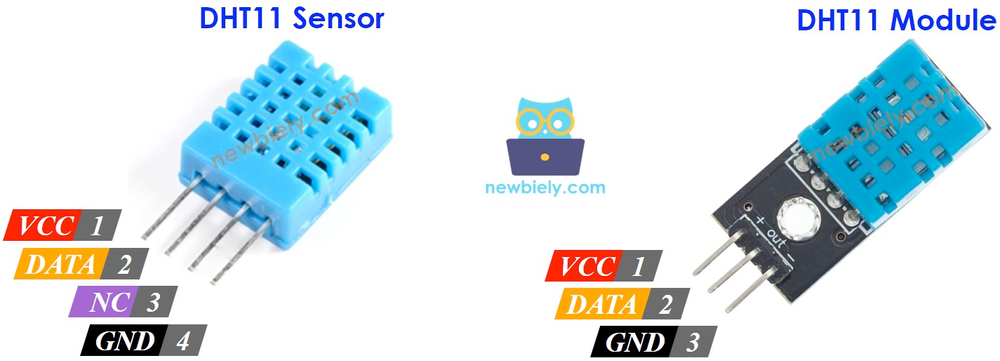
The VCC pin is used to supply power to the sensor, and it typically requires 3.3V or 5V (refer to the datasheet for specific voltage requirements). The GND pin is the ground connection and must be connected to the ground of your ESP32.
The DHT11 pinout is straightforward:
- VCC (Power): Connect to 3.3V or 5V power supply.
- DATA: Outputs digital signal; connect to a digital input on your microcontroller.
- NC (Not Connected): No connection required.
- GND (Ground): Connect to the ground of the microcontroller.
Wiring with ESP32
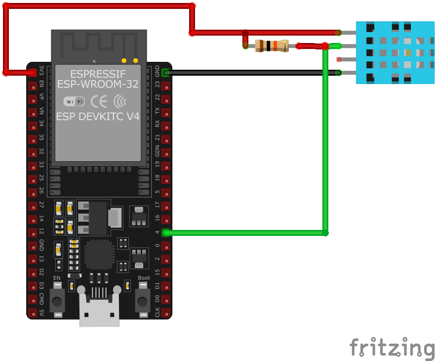
- Connect the
VCCpin to the 3.3V or 5V pin on the ESP32. - Connect the
GNDpin to the ground (GND) of the ESP32. - Connect the
DATApin to a digital GPIO pin on the ESP32 (e.g., GPIO 4). - Place a 10kΩ pull-up resistor between the
DATApin andVCCto ensure reliable communication.
Troubleshooting Guide
Common Issues
❌ Failed to Read from DHT Sensor
Issue: Receiving 'Failed to read from DHT sensor!' or NaN readings when attempting to retrieve data from the DHT11 sensor.
Possible causes include incorrect wiring, insufficient power supply, or improper sensor initialization.
Solution: Double-check the wiring connections: ensure VCC is connected to 5V (or 3.3V if applicable), GND to ground, and the data pin to the appropriate GPIO pin on the microcontroller. Verify that a suitable pull-up resistor (typically 10kΩ) is connected between the data pin and VCC. Ensure the sensor is properly initialized in the code, and that the correct sensor type is specified in the library. Additionally, consider increasing the time between sensor readings, as the DHT11 has a sampling rate of once per second.
⚠️ Inaccurate Humidity Readings
Issue: The DHT11 sensor provides humidity readings that are inconsistent or significantly different from expected values.
Possible causes include the sensor's inherent accuracy limitations, environmental factors, or sensor degradation over time.
Solution: Be aware that the DHT11 has an accuracy of ±5% RH. For improved accuracy, consider using a more precise sensor like the DHT22 or BME280. Ensure the sensor is placed in an environment free from rapid temperature or humidity changes, and avoid placing it near heat sources or in direct sunlight. If the sensor has been in use for an extended period, consider replacing it, as prolonged exposure to high humidity can degrade its performance.
🔋 Power-Related Issues
Issue: The microcontroller resets or the sensor fails to provide readings when additional components, such as servos, are connected.
Possible causes include insufficient power supply or voltage fluctuations caused by high-current components.
Solution: Ensure that the power supply can provide adequate current for all connected components. Use separate power sources for high-current devices like servos, and connect their grounds together with the microcontroller's ground to establish a common reference. Additionally, consider adding decoupling capacitors near the sensor to stabilize the voltage supply.
❌ Sensor Not Detected on I2C Bus
Issue: The DHT11 sensor is not recognized on the I2C bus, leading to communication failures.
Possible causes include incorrect wiring, improper I2C address configuration, or sensor malfunction.
Solution: Verify that the sensor's VCC and GND are properly connected to the power supply, and that SDA and SCL lines are correctly connected to the corresponding I2C pins on the microcontroller. Ensure that the I2C address matches the sensor's default or configured address. Use an I2C scanner to detect the sensor's presence on the bus. If the sensor remains undetected, consider testing with a different microcontroller or replacing the sensor.
Debugging Tips
🔍 Serial Monitor
Use the Serial Monitor to check for error messages and verify the sensor's output. Add debug prints in your code to track the sensor's state.
⚡ Voltage Checks
Use a multimeter to verify voltage levels and check for continuity in your connections. Ensure the power supply is stable and within the sensor's requirements.
Additional Resources
Code Examples
Arduino Example
#include "DHT.h"

#define DHTPIN 4 // Digital pin connected to the DHT sensor
#define DHTTYPE DHT11 // DHT11 sensor type

DHT dht(DHTPIN, DHTTYPE);

void setup() {
  Serial.begin(115200);
  Serial.println("DHT11 Sensor Initialization");
  dht.begin();
}

void loop() {
  delay(2000); // Wait a few seconds between measurements

  float humidity = dht.readHumidity();
  float temperature = dht.readTemperature();

  if (isnan(humidity) || isnan(temperature)) {
    Serial.println("Failed to read from DHT sensor!");
    return;
  }

  Serial.print("Humidity: ");
  Serial.print(humidity);
  Serial.print("%  Temperature: ");
  Serial.print(temperature);
  Serial.println("°C");
}setup() function initializes serial communication and the sensor. In the loop() function, it waits for 2 seconds between measurements, reads humidity and temperature, checks for successful readings, and then prints the values to the Serial Monitor.ESP-IDF Example
#include <stdio.h>
#include "freertos/FreeRTOS.h"
#include "freertos/task.h"
#include "driver/gpio.h"

#define DHT11_PIN GPIO_NUM_4

void dht11_task(void *pvParameter) {
    // DHT11 reading logic here
    while (1) {
        // Read temperature and humidity
        // Print values
        vTaskDelay(2000 / portTICK_PERIOD_MS); // Delay for 2 seconds
    }
}

void app_main() {
    xTaskCreate(&dht11_task, "dht11_task", 2048, NULL, 5, NULL);
}dht11_task function contains the logic to read temperature and humidity from the sensor and print the values. The task runs in an infinite loop with a 2-second delay between readings. The app_main function creates this task with a stack size of 2048 bytes and a priority of 5.ESPHome Example
sensor:
  - platform: dht
    model: DHT11
    pin: GPIO4
    temperature:
      name: "Living Room Temperature"
    humidity:
      name: "Living Room Humidity"
update_interval: 60sdht platform and sets the model to DHT11 for correct handling of the sensor. The pin key defines the GPIO pin (e.g., GPIO4) to which the sensor's data pin is connected. The temperature and humidity keys define the sensor outputs, giving user-friendly names like 'Living Room Temperature' and 'Living Room Humidity.' The update_interval is set to 60 seconds, which means the ESP32 will read and update the sensor data every 60 seconds.PlatformIO Example
platformio.ini
[env:esp32dev]
platform = espressif32
board = esp32dev
framework = arduino
lib_deps =
    adafruit/DHT sensor library @ ^1.4.3
    adafruit/Adafruit Unified Sensor @ ^1.1.6
monitor_speed = 115200
PlatformIO Example Code
#include <Adafruit_Sensor.h>
#include <DHT.h>
#include <DHT_U.h>

#define DHTPIN 4 // Define the GPIO pin for the data pin
#define DHTTYPE DHT11 // Specify the DHT model

DHT dht(DHTPIN, DHTTYPE);

void setup() {
    Serial.begin(115200);
    Serial.println("DHT11 Sensor Example");

    // Initialize the sensor
    dht.begin();
}

void loop() {
    // Read temperature and humidity
    float temperature = dht.readTemperature();
    float humidity = dht.readHumidity();

    // Check if any readings failed
    if (isnan(temperature) || isnan(humidity)) {
        Serial.println("Failed to read from DHT sensor!");
        return;
    }

    // Print results to Serial Monitor
    Serial.print("Temperature: ");
    Serial.print(temperature);
    Serial.println(" °C");

    Serial.print("Humidity: ");
    Serial.print(humidity);
    Serial.println(" %");

    delay(2000); // Wait before next reading
}platform = espressif32 specifies that the project is for ESP32 boards, and board = esp32dev sets the specific development board being used. The lib_deps field includes the required libraries for the DHT11 sensor (DHT sensor library and Adafruit Unified Sensor), ensuring compatibility. The code defines the GPIO pin (e.g., GPIO4) for the sensor’s data line and initializes the DHT11 sensor using the DHT library. Temperature and humidity readings are printed to the Serial Monitor every 2 seconds, with error handling to check for invalid readings.MicroPython Example
from machine import Pin
from time import sleep
import dht

# Initialize the DHT11 sensor on GPIO4
dht_sensor = dht.DHT11(Pin(4))

print("DHT11 Sensor Example")

while True:
    try:
        # Measure temperature and humidity
        dht_sensor.measure()
        temperature = dht_sensor.temperature()  # Temperature in Celsius
        humidity = dht_sensor.humidity()  # Relative Humidity in %

        # Print temperature and humidity to the console
        print("Temperature: {:.1f} °C".format(temperature))
        print("Humidity: {:.1f} %".format(humidity))
    except OSError as e:
        print("Failed to read sensor.")

    # Delay between readings
sleep(2)dht module simplifies interactions with the DHT11 sensor, handling initialization and data retrieval. The sensor is initialized with the GPIO pin (e.g., GPIO4), and a confirmation message is printed to indicate successful setup. Inside an infinite loop, the script continuously reads the temperature (in Celsius) and relative humidity (in percentage) using the measure() method. The readings are formatted and printed to the console. Error handling with try and except ensures the program can recover from sensor read failures. A 2-second delay between readings ensures manageable updates.Conclusion
The ESP32 DHT11 Temperature and Humidity Sensor is a powerful environment sensor that offers excellent performance and reliability. With support for multiple development platforms including Arduino, ESP-IDF, ESPHome, PlatformIO, and MicroPython, it's a versatile choice for your IoT projects.
For optimal performance, ensure proper wiring and follow the recommended configuration for your chosen development platform.
Always verify power supply requirements and pin connections before powering up your project to avoid potential damage.
