ESP32 KY-023 Dual Axis Joystick Module
Overview
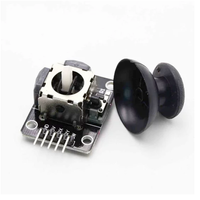
The KY-023 is a dual-axis joystick module that provides analog outputs for X and Y positions, along with a digital output for a built-in push-button. It's ideal for applications requiring directional input, such as remote controls, gaming interfaces, and robotic navigation.


About KY-023 Dual Axis Joystick Module
The KY-023 Dual Axis Joystick Module is an input device that combines two potentiometers and a push-button switch, allowing for control in both the X and Y axes. Each axis corresponds to a potentiometer that outputs an analog voltage, which can be read by microcontrollers like the Arduino or ESP32. The module also features a push-button that activates when the joystick is pressed down. This joystick is commonly used in robotics, gaming, and other interactive projects.
Where to Buy

Starting from
$2 per unit


Prices are subject to change. We earn from qualifying purchases as an Amazon Associate.
Technical Specifications
Pinout Configuration
The VCC pin is used to supply power to the sensor, and it typically requires 3.3V or 5V (refer to the datasheet for specific voltage requirements). The GND pin is the ground connection and must be connected to the ground of your ESP32.
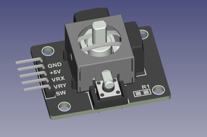
GND:Connects to ground.+5V:Connects to 5V power supply.VRx:Outputs analog voltage corresponding to X-axis position.VRy:Outputs analog voltage corresponding to Y-axis position.SW:Digital output for the push-button; active low when pressed.
Wiring with ESP32
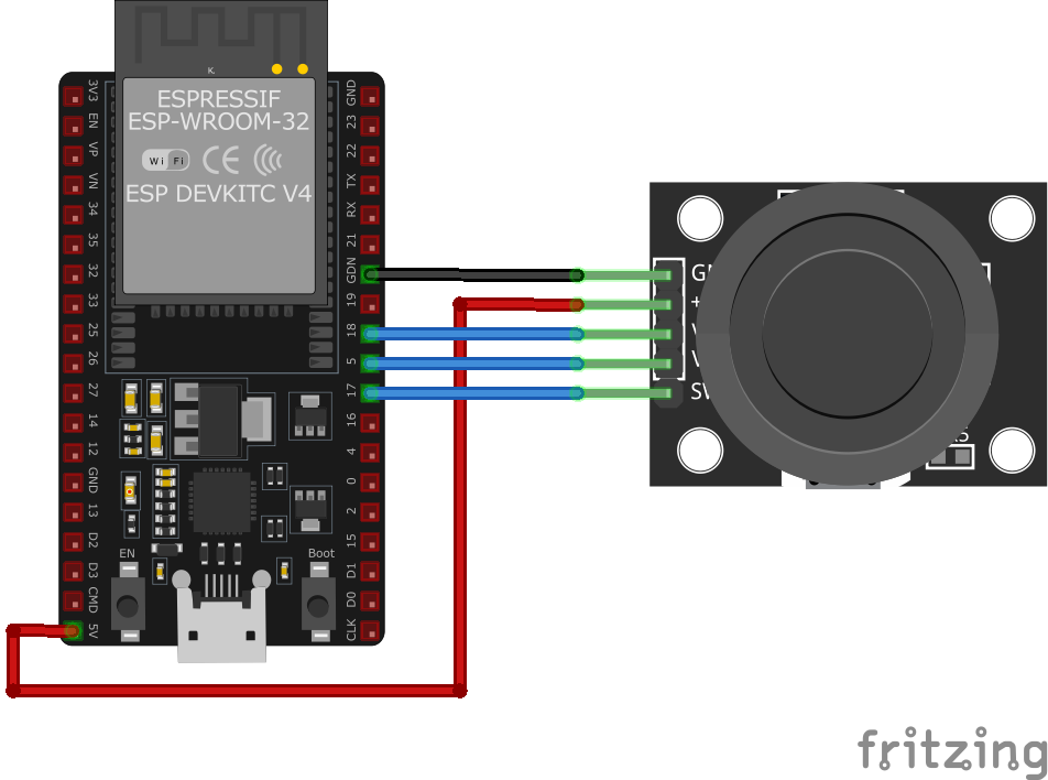
GND:Connect to ESP32GND.+5V:Connect to ESP323.3Vor5V(ensure voltage compatibility).VRx:Connect to an analog input pin on ESP32 (e.g.,GPIO36).VRy:Connect to another analog input pin on ESP32 (e.g.,GPIO39).SW:Connect to a digital input pin on ESP32 (e.g.,GPIO34); configure with an internal pull-up resistor.
Troubleshooting Guide
Common Issues
❌ Joystick Not Responding
Issue: No change in analog readings when moving the joystick.
Solutions:
- Verify all connections are secure and correctly placed.
- Ensure the module is receiving the appropriate voltage (3.3V or 5V).
- Check that the microcontroller's analog input pins are correctly configured.
- Test the joystick with a multimeter to confirm the potentiometers are functioning.
❓ Button Not Registering Presses
Issue: The push-button does not trigger any response.
Solutions:
- Ensure the SW pin is connected to a digital input configured with a pull-up resistor.
- Check for continuity in the button circuit using a multimeter.
- Confirm that the microcontroller's digital input pin is correctly configured in the code.
Debugging Tips
🔍 Serial Monitor
Use the Serial Monitor to check for error messages and verify the sensor's output. Add debug prints in your code to track the sensor's state.
⚡ Voltage Checks
Use a multimeter to verify voltage levels and check for continuity in your connections. Ensure the power supply is stable and within the sensor's requirements.
Additional Resources
Code Examples
Arduino Example
// Declaration and initialization of the input pins
int JoyStick_X = A0; // X-axis signal
int JoyStick_Y = A1; // Y-axis signal
int Button = 3; // Button

void setup() {
    pinMode(JoyStick_X, INPUT);
    pinMode(JoyStick_Y, INPUT);
    pinMode(Button, INPUT_PULLUP); // Enable internal pull-up resistor
    Serial.begin(9600); // Serial output with 9600 bps
}

void loop() {
    float x, y;
    int buttonState;
    // Read current values and convert to voltage
    x = analogRead(JoyStick_X)  (5.0 / 1023.0);
    y = analogRead(JoyStick_Y)  (5.0 / 1023.0);
    buttonState = digitalRead(Button);
    // Output the values
    Serial.print("X-axis:"); Serial.print(x, 4); Serial.print("V, ");
    Serial.print("Y-axis:"); Serial.print(y, 4); Serial.print("V, ");
    Serial.print("Button:");
    if (buttonState == HIGH) {
        Serial.println("not pressed");
    } else {
        Serial.println("pressed");
    }
    delay(200);
}
This Arduino code reads the analog values from the X and Y axes of the KY-023 joystick and the digital state of the push-button. It then prints the corresponding voltage levels and button state to the serial monitor.
ESP-IDF Example
#include <stdio.h>
#include "freertos/FreeRTOS.h"
#include "freertos/task.h"
#include "driver/adc.h"
#include "driver/gpio.h"

#define JOYSTICK_X ADC1_CHANNEL_0 // GPIO36
#define JOYSTICK_Y ADC1_CHANNEL_3 // GPIO39
#define BUTTON GPIO_NUM_34

void app_main(void) {
    adc1_config_width(ADC_WIDTH_BIT_12);
    adc1_config_channel_atten(JOYSTICK_X, ADC_ATTEN_DB_11);
    adc1_config_channel_atten(JOYSTICK_Y, ADC_ATTEN_DB_11);
    gpio_set_direction(BUTTON, GPIO_MODE_INPUT);
    gpio_pulldown_en(BUTTON);

    printf("KY-023 Joystick Test\n");
    while (1) {
        int x_value = adc1_get_raw(JOYSTICK_X);
        int y_value = adc1_get_raw(JOYSTICK_Y);
        int button_state = gpio_get_level(BUTTON);
        printf("X: %d, Y: %d, Button: %s\n", x_value, y_value, button_state ? "Not Pressed" : "Pressed");
        vTaskDelay(pdMS_TO_TICKS(200));
    }
}
This ESP-IDF code reads analog values from the KY-023 joystick's X and Y axes using ADC1 on GPIO36 and GPIO39. It also monitors the push-button state on GPIO34 and prints the readings to the console every 200ms.
ESPHome Example
sensor:
  - platform: adc
    pin: GPIO36
    name: "KY-023 Joystick X-Axis"
    update_interval: 200ms
  - platform: adc
    pin: GPIO39
    name: "KY-023 Joystick Y-Axis"
    update_interval: 200ms
binary_sensor:
  - platform: gpio
    pin:
      number: GPIO34
      mode: INPUT_PULLUP
    name: "KY-023 Joystick Button"
This ESPHome configuration sets up the KY-023 joystick module on ESP32. It reads the X and Y-axis values as analog inputs and detects button presses on GPIO34, logging the results every 200ms.
PlatformIO Example
platformio.ini
[env:esp32]
platform = espressif32
board = esp32dev
framework = arduino
PlatformIO Example Code
#include <Arduino.h>

#define JOYSTICK_X A0
#define JOYSTICK_Y A1
#define BUTTON 3

void setup() {
    pinMode(JOYSTICK_X, INPUT);
    pinMode(JOYSTICK_Y, INPUT);
    pinMode(BUTTON, INPUT_PULLUP);
    Serial.begin(115200);
    Serial.println("KY-023 Joystick Module Test");
}

void loop() {
    int x_value = analogRead(JOYSTICK_X);
    int y_value = analogRead(JOYSTICK_Y);
    int button_state = digitalRead(BUTTON);
    Serial.printf("X: %d, Y: %d, Button: %s\n", x_value, y_value, button_state ? "Not Pressed" : "Pressed");
    delay(200);
}
This PlatformIO code reads the analog values of the KY-023 joystick's X and Y axes and detects button presses. It prints the readings to the serial monitor every 200ms.
MicroPython Example
import machine
import time

JOYSTICK_X = machine.ADC(machine.Pin(36))
JOYSTICK_Y = machine.ADC(machine.Pin(39))
BUTTON = machine.Pin(34, machine.Pin.IN, machine.Pin.PULL_UP)

JOYSTICK_X.atten(machine.ADC.ATTN_11DB)
JOYSTICK_Y.atten(machine.ADC.ATTN_11DB)

while True:
    x_value = JOYSTICK_X.read()
    y_value = JOYSTICK_Y.read()
    button_state = BUTTON.value()
    print("X:", x_value, "Y:", y_value, "Button:", "Not Pressed" if button_state else "Pressed")
    time.sleep(0.2)
This MicroPython script reads the analog values of the KY-023 joystick's X and Y axes using ADC on GPIO36 and GPIO39. It also monitors button presses on GPIO34 and prints the results every 200ms.
Conclusion
The ESP32 KY-023 Dual Axis Joystick Module is a powerful KY-0xx module sensor that offers excellent performance and reliability. With support for multiple development platforms including Arduino, ESP-IDF, ESPHome, PlatformIO, and MicroPython, it's a versatile choice for your IoT projects.
For optimal performance, ensure proper wiring and follow the recommended configuration for your chosen development platform.
Always verify power supply requirements and pin connections before powering up your project to avoid potential damage.