
KY-016 RGB Full Color LED Module
The KY-016 is an RGB LED module that can display a wide range of colors by adjusting the brightness of its red, green, and blue LEDs. It's suitable for various applications requiring colorful visual feedback.

KY-016 pinout
The KY-016 is a 4-pin RGB LED module with common cathode configuration:
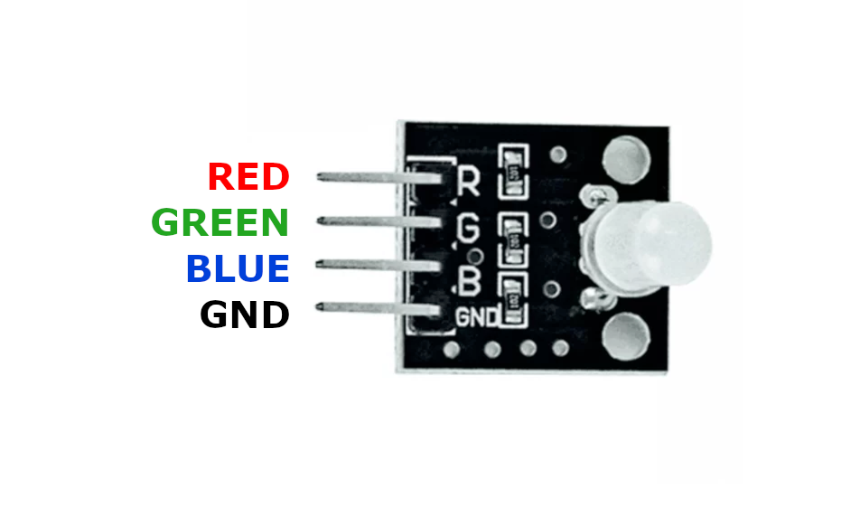
| Pin | Type | Description | Notes |
|---|---|---|---|
| Pin 1 (GND) | Power | Common cathode (ground) | Connect to GND |
| Pin 2 (R) | Communication | Red LED anode | 1.8V forward voltage, 180Ω resistor |
| Pin 3 (G) | Communication | Green LED anode | 2.8V forward voltage, 100Ω resistor |
| Pin 4 (B) | Communication | Blue LED anode | 2.8V forward voltage, 100Ω resistor |
Interface: PWM control for each color channel
Colors: 16.7 million colors via RGB mixing
Configuration: Common cathode (GND shared)
Current: 20mA per channel
Resistors: R=180Ω (1.8V), G=100Ω (2.8V), B=100Ω (2.8V)
Applications: Mood lighting, status indicators, decorative effects, color displays
Wiring the KY-016 to ESP32
To interface the KY-016 with an ESP32 for RGB color control:
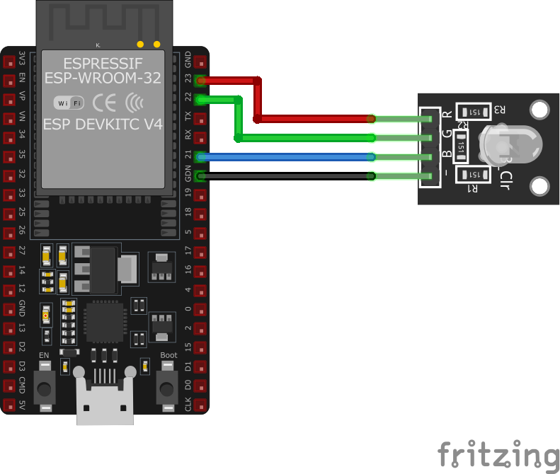
| KY-016 pin | ESP32 pin | Purpose |
|---|---|---|
| Pin 1 (GND) | GND | Common ground |
| Pin 2 (R) | GPIO25 | Red channel (via 180Ω resistor) |
| Pin 3 (G) | GPIO26 | Green channel (via 100Ω resistor) |
| Pin 4 (B) | GPIO27 | Blue channel (via 100Ω resistor) |
Current-Limiting Resistors: Red=180Ω, Green/Blue=100Ω (required for LED protection)
PWM Control: Use PWM on all three GPIO pins for color mixing
GPIO Selection: Use any PWM-capable GPIOs, shown pins are examples
3.3V Logic: ESP32’s 3.3V output is sufficient with proper resistors
KY-016 code examples
#define RED_PIN 25   // GPIO25, matches the wiring above
#define GREEN_PIN 26 // GPIO26
#define BLUE_PIN 27  // GPIO27

void setup() {
    pinMode(RED_PIN, OUTPUT);
    pinMode(GREEN_PIN, OUTPUT);
    pinMode(BLUE_PIN, OUTPUT);
}

void loop() {
    analogWrite(RED_PIN, 255);   // Red at full brightness
    analogWrite(GREEN_PIN, 0);   // Green off
    analogWrite(BLUE_PIN, 0);    // Blue off
    delay(1000);
    analogWrite(RED_PIN, 0);
    analogWrite(GREEN_PIN, 255); // Green at full brightness
    analogWrite(BLUE_PIN, 0);
    delay(1000);
    analogWrite(RED_PIN, 0);
    analogWrite(GREEN_PIN, 0);
    analogWrite(BLUE_PIN, 255);  // Blue at full brightness
    delay(1000);
}
This Arduino code sets up the KY-016 RGB LED module by defining the pins connected to the red, green, and blue LEDs. In the loop, it cycles through red, green, and blue colors, each displayed for one second.
#include <stdio.h>
#include "freertos/FreeRTOS.h"
#include "freertos/task.h"
#include "driver/ledc.h"

#define RED_PIN GPIO_NUM_25
#define GREEN_PIN GPIO_NUM_26
#define BLUE_PIN GPIO_NUM_27
#define LEDC_TIMER LEDC_TIMER_0
#define LEDC_MODE LEDC_HIGH_SPEED_MODE
#define LEDC_CHANNEL_R LEDC_CHANNEL_0
#define LEDC_CHANNEL_G LEDC_CHANNEL_1
#define LEDC_CHANNEL_B LEDC_CHANNEL_2

void configure_led_pwm(gpio_num_t pin, ledc_channel_t channel) {
    ledc_timer_config_t ledc_timer = {
        .speed_mode = LEDC_MODE,
        .timer_num = LEDC_TIMER,
        .duty_resolution = LEDC_TIMER_8_BIT,
        .freq_hz = 5000,
        .clk_cfg = LEDC_AUTO_CLK
    };
    ledc_timer_config(&ledc_timer);

    ledc_channel_config_t ledc_channel = {
        .gpio_num = pin,
        .speed_mode = LEDC_MODE,
        .channel = channel,
        .intr_type = LEDC_INTR_DISABLE,
        .timer_sel = LEDC_TIMER,
        .duty = 0,
        .hpoint = 0
    };
    ledc_channel_config(&ledc_channel);
}

void set_color(uint32_t red, uint32_t green, uint32_t blue) {
    ledc_set_duty(LEDC_MODE, LEDC_CHANNEL_R, red);
    ledc_update_duty(LEDC_MODE, LEDC_CHANNEL_R);
    ledc_set_duty(LEDC_MODE, LEDC_CHANNEL_G, green);
    ledc_update_duty(LEDC_MODE, LEDC_CHANNEL_G);
    ledc_set_duty(LEDC_MODE, LEDC_CHANNEL_B, blue);
    ledc_update_duty(LEDC_MODE, LEDC_CHANNEL_B);
}

void app_main(void) {
    configure_led_pwm(RED_PIN, LEDC_CHANNEL_R);
    configure_led_pwm(GREEN_PIN, LEDC_CHANNEL_G);
    configure_led_pwm(BLUE_PIN, LEDC_CHANNEL_B);

    while (1) {
        set_color(255, 0, 0);  // Red
        vTaskDelay(pdMS_TO_TICKS(1000));
        set_color(0, 255, 0);  // Green
        vTaskDelay(pdMS_TO_TICKS(1000));
        set_color(0, 0, 255);  // Blue
        vTaskDelay(pdMS_TO_TICKS(1000));
    }
}
This ESP-IDF code configures the KY-016 RGB LED module using PWM on GPIO25 (red), GPIO26 (green), and GPIO27 (blue). The configure_led_pwm() function sets up the PWM channels for each LED, while set_color() adjusts the brightness of each color. The LED cycles through red, green, and blue every second.
output:
  - platform: ledc
    pin: GPIO25
    id: red_led
  - platform: ledc
    pin: GPIO26
    id: green_led
  - platform: ledc
    pin: GPIO27
    id: blue_led

light:
  - platform: rgb
    name: "KY-016 RGB LED"
    red: red_led
    green: green_led
    blue: blue_led
    gamma_correct: 2.8
This ESPHome configuration sets up the KY-016 RGB LED module using PWM on GPIO25, GPIO26, and GPIO27. The LED's color can be adjusted through Home Assistant, allowing full RGB control.
[env:esp32]
platform = espressif32
board = esp32dev
framework = arduino#include <Arduino.h>
#define RED_PIN 25
#define GREEN_PIN 26
#define BLUE_PIN 27
void setup() {
pinMode(RED_PIN, OUTPUT);
pinMode(GREEN_PIN, OUTPUT);
pinMode(BLUE_PIN, OUTPUT);
}
void loop() {
analogWrite(RED_PIN, 255);
analogWrite(GREEN_PIN, 0);
analogWrite(BLUE_PIN, 0);
delay(1000);
analogWrite(RED_PIN, 0);
analogWrite(GREEN_PIN, 255);
analogWrite(BLUE_PIN, 0);
delay(1000);
analogWrite(RED_PIN, 0);
analogWrite(GREEN_PIN, 0);
analogWrite(BLUE_PIN, 255);
delay(1000);
}This PlatformIO code configures the KY-016 RGB LED module on GPIO25, GPIO26, and GPIO27. The LED cycles through red, green, and blue every second using PWM signals.
import machine
import time

RED_PIN = machine.PWM(machine.Pin(25), freq=1000)
GREEN_PIN = machine.PWM(machine.Pin(26), freq=1000)
BLUE_PIN = machine.PWM(machine.Pin(27), freq=1000)

def set_color(r, g, b):
    RED_PIN.duty(r)
    GREEN_PIN.duty(g)
    BLUE_PIN.duty(b)

while True:
    set_color(1023, 0, 0)  # Red
    time.sleep(1)
    set_color(0, 1023, 0)  # Green
    time.sleep(1)
    set_color(0, 0, 1023)  # Blue
    time.sleep(1)
This MicroPython script configures GPIO25, GPIO26, and GPIO27 as PWM outputs for the KY-016 RGB LED module. The set_color() function controls the brightness of each LED channel, cycling through red, green, and blue every second.
KY-016 specifications
About the KY-016
The KY-016 is a 5mm through-hole RGB LED - red, green, and blue dies in one common-cathode package - broken out to a 4-pin header alongside three onboard current-limiting resistors (labeled R1-R3 on the board itself), so unlike its SMD sibling the KY-009, this one drives safely straight off a GPIO with nothing extra to add. Forward voltages still differ per die - 1.8V for red, 2.8V for green and blue - which is why the resistors are sized differently per channel, but since they’re already picked and mounted, wiring is just the shared cathode to GND and each color leg to a PWM-capable pin.
The tradeoff for that convenience is a fixed forward current chosen by whoever populated the board, not something you can retune the way you could with your own resistors, and the domed 5mm package throws a narrower, more directional beam than the KY-009’s wide-angle SMD diffusion. Both modules use the same per-channel PWM approach to mix colors - the ESP32’s ledc peripheral has plenty of channels for three simultaneous outputs.
KY-016 troubleshooting
LED Not Lighting Up
›
Issue: The LED does not turn on.
Solutions:
- Verify all connections are secure and correctly placed.
- Ensure appropriate current-limiting resistors are used for each LED channel.
- Check that the GPIO pins are correctly configured as outputs in the code.
Incorrect Colors Displayed
›
Issue: The LED displays unexpected colors.
Solutions:
- Confirm that the PWM signals are correctly set for each color channel.
- Ensure that the correct GPIO pins are assigned to the respective LED colors in the code.
- Check for any short circuits or incorrect wiring between the LED pins.
Where to buy the KY-016

Resources
Similar sensors


