LD2450 Human Presence Sensor
View on Amazon
Overview
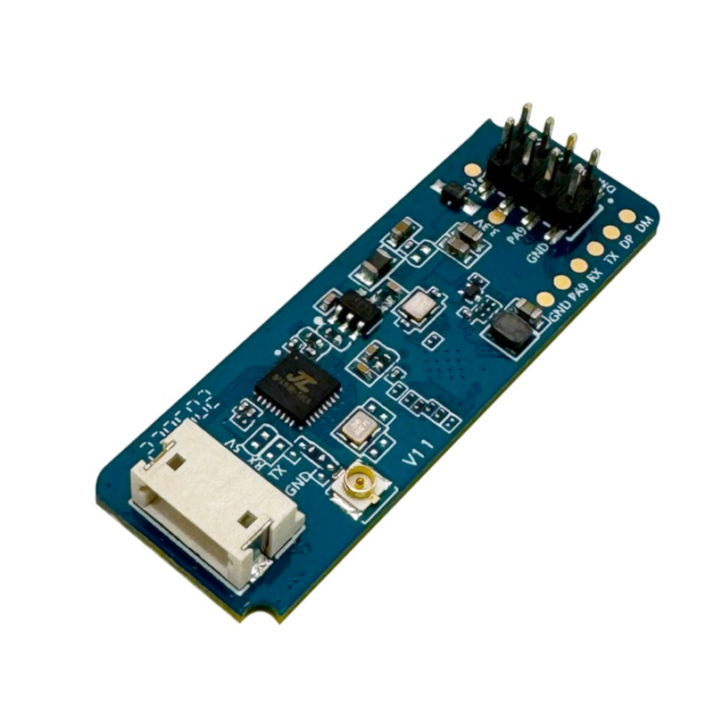
About LD2450 Human Presence Sensor
The LD2450 is a 24GHz mmWave radar sensor capable of tracking up to three human targets simultaneously, providing real-time data on position, speed, and movement. It utilizes FMCW technology and supports both UART and Bluetooth Low Energy (BLE) communication. The sensor is ideal for applications requiring precise motion tracking, such as smart lighting, occupancy detection, and automation systems. For more information on the LD2450 series, see LD2450.
Get Your LD2450


💡 Prices are subject to change. We earn from qualifying purchases as an Amazon Associate.
LD2450 Specifications
Complete technical specification details for LD2450 Human Presence Sensor
📊 Technical Parameters
LD2450 Pinout
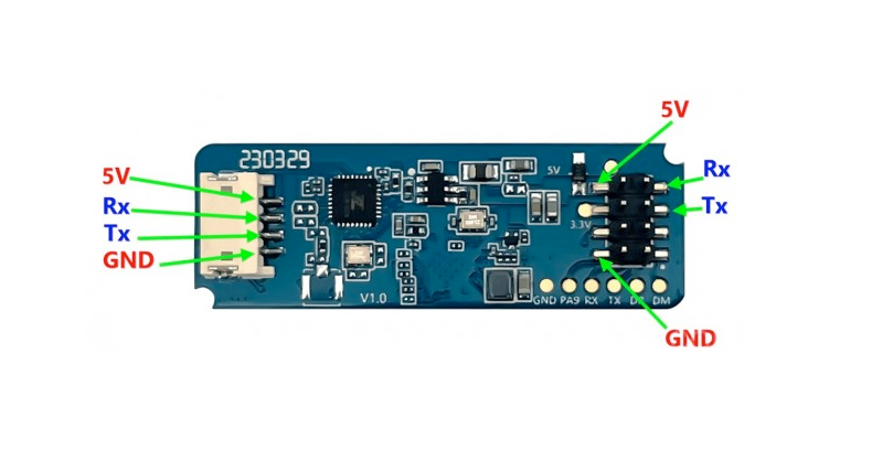
The **LD2450** is a 4-pin 24GHz mmWave multi-target tracker with BLE:
Visual Pinout Diagram
Pin Types
Quick Tips
**Interface**: UART (256000 baud) + BLE,📡 **Technology**: 24GHz FMCW radar,👥 **Multi-Target**: Tracks up to 3 human targets simultaneously,📍 **Position Data**: Real-time X, Y coordinates for each target
**Speed Tracking**: Movement speed for each tracked target,📏 **Range**: Precise motion tracking within detection zone,⚡ **Power**: 5V DC (required for radar and BLE)
**Bluetooth**: Built-in BLE for wireless configuration,💡 **No OUT Pin**: Uses only UART for data (no digital output pin),🎯 **Applications**: Multi-occupancy detection, smart lighting zones, security systems
Pin Descriptions
| Pin Name | Type | Description | Notes |
|---|---|---|---|
1 5V | Power | Power input | 5V DC regulated power supply |
2 GND | Power | Ground connection | |
3 TX | Communication | UART transmit | Sends target tracking data (connect to ESP32 RX) |
4 RX | Communication | UART receive | Receives commands (connect to ESP32 TX) |
Wiring LD2450 to ESP32
To interface the **LD2450** with an **ESP32** for multi-target tracking via UART:
Visual Wiring Diagram

Connection Status
Protocol
Pin Connections
| LD2450 Pin | Connection | ESP32 Pin | Description |
|---|---|---|---|
1 5V Required | 5V | Power supply (5V regulated) | |
2 GND Required | GND | Ground | |
3 TX Required | GPIO16 (RX2) | Sensor transmit to ESP32 receive | |
4 RX Required | GPIO17 (TX2) | Sensor receive from ESP32 transmit |
**UART2**: Use UART2 on ESP32 (GPIO16/17 are default UART2 pins)
**Baud Rate**: 256000 bps, no parity, 1 stop bit
**Power**: Requires clean regulated 5V supply for radar + BLE
**TX/RX**: Connect sensor TX to ESP32 RX, sensor RX to ESP32 TX
**Multi-Target**: Receives data for up to 3 tracked individuals
**Data Format**: X/Y position coordinates and speed for each target
**BLE**: Use for configuration/debugging (no pin wiring needed)
**Bluetooth**: Ensure ESP32 BLE doesn't conflict with UART if both active
LD2450 Troubleshooting
Common issues and solutions to help you get your sensor working
Common Issues
Issue: The ESP32 receives no data from the sensor.
Ensure correct wiring: verify that TX and RX are properly connected. Confirm that the UART is configured with the correct baud rate (256000), no parity, and 1 stop bit. Also, ensure that the sensor is powered with 5V DC.
Issue: The sensor does not detect presence even when someone is in range.
Check the sensor's field of view and ensure there are no obstructions. Verify that the sensor's firmware is up to date and that the configuration settings are appropriate for the detection range and sensitivity required.
Issue: Sensor intermittently detects presence or fails to maintain detection.
Ensure stable power supply and UART communication. Check for environmental factors that may cause interference, such as reflective surfaces or moving objects outside the intended detection area.
Issue: Unable to connect to the sensor via BLE.
Ensure that the ESP32's Bluetooth is enabled and that the sensor is in range. Verify that the correct BLE address is being used and that there are no other devices interfering with the connection.
Debugging Tips
Use the Serial Monitor to check for error messages and verify the sensor's output. Add debug prints in your code to track the sensor's state.
Use a multimeter to verify voltage levels and check for continuity in your connections. Ensure the power supply is stable and within the sensor's requirements.
Additional Resources
LD2450 Programming Examples
Ready-to-use code examples for different platforms and frameworks
#include <HLK_LD2450.h>

HLK_LD2450 radar;

void setup() {
  Serial.begin(115200);
  Serial2.begin(256000, SERIAL_8N1, 16, 17);
  radar.begin(Serial2);
}

void loop() {
  radar.read();
  for (int i = 0; i < radar.getTargetCount(); i++) {
    Serial.print("Target ");
    Serial.print(i);
    Serial.print(": X=");
    Serial.print(radar.getTargetX(i));
    Serial.print(" Y=");
    Serial.print(radar.getTargetY(i));
    Serial.print(" Speed=");
    Serial.println(radar.getTargetSpeed(i));
  }
  delay(500);
}
This Arduino example utilizes the HLK_LD2450 library to interface with the LD2450 sensor over UART. It initializes communication on Serial2 with a baud rate of 256000 and reads data for up to three targets, printing their X and Y coordinates and speed to the serial monitor. Ensure that the sensor is connected to GPIO16 (RX) and GPIO17 (TX) on the ESP32. The library can be found at RBEGamer/HLK-LD2450.
uart:
  id: uart_bus
  tx_pin: GPIO17
  rx_pin: GPIO16
  baud_rate: 256000

ld2450:
  uart_id: uart_bus

sensor:
  - platform: ld2450
    target:
      id: target1
      name: "Target 1"
    target:
      id: target2
      name: "Target 2"
    target:
      id: target3
      name: "Target 3"
This ESPHome configuration sets up the LD2450 sensor over UART, using GPIO17 for TX and GPIO16 for RX at a baud rate of 256000. The ld2450 component is initialized with the UART bus, and three targets are defined to track up to three individuals simultaneously. Each target's data, including position and speed, can be accessed in Home Assistant for automation purposes. For more details, refer to the ESPHome documentation: ESPHome LD2450 Sensor Component.
platformio.ini
[env:esp32dev]
platform = espressif32
board = esp32dev
framework = arduino
lib_deps =
    rbegamer/HLK-LD2450
monitor_speed = 115200
main.cpp
#include <HLK_LD2450.h>

HLK_LD2450 radar;

void setup() {
  Serial.begin(115200);
  Serial2.begin(256000, SERIAL_8N1, 16, 17);
  radar.begin(Serial2);
}

void loop() {
  radar.read();
  for (int i = 0; i < radar.getTargetCount(); i++) {
    Serial.print("Target ");
    Serial.print(i);
    Serial.print(": X=");
    Serial.print(radar.getTargetX(i));
    Serial.print(" Y=");
    Serial.print(radar.getTargetY(i));
    Serial.print(" Speed=");
    Serial.println(radar.getTargetSpeed(i));
  }
  delay(500);
}
This PlatformIO example uses the HLK_LD2450 library to communicate with the LD2450 sensor over UART. It initializes Serial2 with a baud rate of 256000 and reads data for up to three targets, printing their positions and speeds to the serial monitor. Ensure that the sensor is connected to GPIO16 (RX) and GPIO17 (TX) on the ESP32. The library is available on the PlatformIO Registry: HLK-LD2450 PlatformIO Library.
from machine import UART
import time

uart = UART(2, baudrate=256000, tx=17, rx=16)

while True:
    if uart.any():
        data = uart.read()
        if data:
            print(data)
    time.sleep(0.5)
This MicroPython code initializes UART2 on an ESP32 using GPIO17 for TX and GPIO16 for RX, configured at a baud rate of 256000. It reads raw byte data from the LD2450 sensor and prints it to the console. This can be used for debugging or as a base for parsing structured radar output. For a more complete implementation, refer to the MicroPython driver available at csRon/HLK-LD2450.
Wrapping Up LD2450
The ESP32 LD2450 Human Presence Sensor is a powerful Human Presence sensor that offers excellent performance and reliability. With support for multiple development platforms including Arduino, ESP-IDF, ESPHome, PlatformIO, and MicroPython, it's a versatile choice for your IoT projects.
Best Practices
For optimal performance, ensure proper wiring and follow the recommended configuration for your chosen development platform.
Safety First
Always verify power supply requirements and pin connections before powering up your project to avoid potential damage.
Ready to Start Building?
Now that you have all the information you need, it's time to integrate the LD2450 into your ESP32 project and bring your ideas to life!
Explore Alternative Sensors
Looking for alternatives to the LD2450? Check out these similar sensors that might fit your project needs.
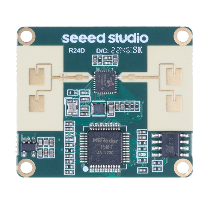
MR24HPC1 Human Static Presence Radar Sensor
The MR24HPC1 is a high-sensitivity 24GHz radar sensor capable of detecting human presence and motion. It communicates via UART and is ideal...
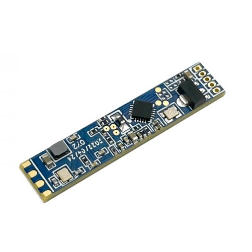
LD2410B Human Presence Sensor
The LD2410B is a millimeter-wave radar sensor for human presence detection with enhanced Bluetooth-based configuration support. It maintains...
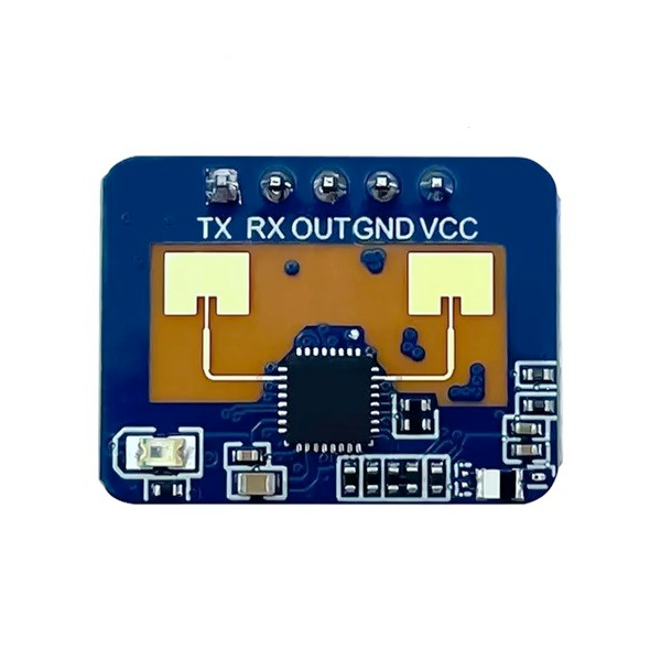
LD2410C Human Presence Sensor
The LD2410C is a millimeter-wave radar sensor for human presence detection, supporting both stationary and moving target detection. It uses...


