
PCA9685 16-Channel 12-bit PWM/Servo Driver
The PCA9685 is a 16-channel, 12-bit PWM controller from NXP, widely used to control servos, LEDs, and other PWM devices. It communicates over I²C and works with popular microcontrollers including ESP32, Arduino, Raspberry Pi, and more. Its adjustable PWM frequency (24 Hz to 1526 Hz) and precise 12-bit resolution make it ideal for robotics, lighting, and automation projects.

PCA9685 pinout
The PCA9685 has multiple pins for I²C communication, external power, and 16 PWM output channels.
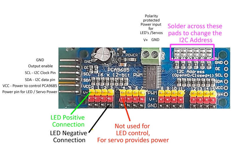
| Pin | Type | Description | Notes |
|---|---|---|---|
| VCC | Power | Logic power supply (2.3V-5.5V). Connect to 3.3V or 5V. | Powers the I²C logic and PWM circuitry. |
| GND | Power | Ground connection. Connect to microcontroller and power supply ground. | Common ground for all devices. |
| SDA | I2C | I²C Serial Data line. Bidirectional data communication. | Connect to ESP32 GPIO 21 (default SDA). |
| SCL | I2C | I²C Serial Clock line. Clock signal for I²C communication. | Connect to ESP32 GPIO 22 (default SCL). |
| V+ | Power | External power for servos/LEDs (5V-6V). Separate from VCC logic power. | Required for high-current devices. Use regulated power supply. |
| Outputs 0-15 | PWM | 16 independent PWM output channels. Each generates 12-bit (4096 steps) PWM signals. | Connect to servo signal wires, LED anodes, or other PWM devices. |
| OE | Control | Output Enable (active low). Pull low to disable all PWM outputs. | Optional - usually left unconnected or pulled high. |
| ADR (A0-A5) | Address | I²C address selection pins. Solder bridges to set custom address. | Default address: 0x40. Can address up to 62 modules (0x40-0x7F). |
I²C address: 0x40 (default), configurable via A0-A5 solder pads
PWM resolution: 12-bit (4096 steps)
PWM frequency: 24 Hz to 1526 Hz (adjustable)
16 independent PWM channels
Up to 62 modules can share same I²C bus
External V+ required for servos and high-current LEDs
Wiring the PCA9685 to ESP32
To interface the PCA9685 with an ESP32, connect VCC to 3.3V or 5V, GND to ground, SDA to GPIO 21, SCL to GPIO 22, and V+ to an external 5-6V power supply for servos/LEDs.
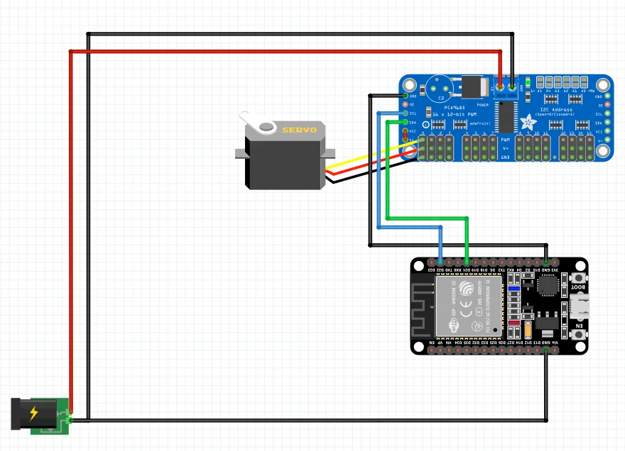
| PCA9685 pin | ESP32 pin | Purpose |
|---|---|---|
| VCC | 3.3V or 5V | Logic power supply. Use 3.3V or 5V depending on your setup. |
| GND | GND | Ground connection. Must be common with ESP32 and external power. |
| SDA | GPIO 21 | I²C data line. Use pull-up resistors (4.7kΩ recommended). |
| SCL | GPIO 22 | I²C clock line. Use pull-up resistors (4.7kΩ recommended). |
| V+ | External 5-6V Supply | External power for servos/LEDs. Do NOT use ESP32 5V pin for multiple devices. |
| OE | Optional GPIO | Output enable control. Pull low to disable all outputs. · optional |
I²C pull-up resistors (4.7kΩ) required on SDA and SCL lines
Default I²C address: 0x40 (can be changed via address pins)
CRITICAL: Use external power supply for V+ when controlling multiple servos
Connect all grounds together: ESP32, PCA9685, and external power supply
Add 470µF-1000µF capacitor across V+ and GND to stabilize power
PWM frequency for servos: 50Hz (standard)
Maximum current per channel: 25mA (total board: 400mA)
Chain up to 62 PCA9685 boards on same I²C bus
PCA9685 code examples
#include <Wire.h>
#include <Adafruit_PWMServoDriver.h>

// Create a PCA9685 object
Adafruit_PWMServoDriver pwm = Adafruit_PWMServoDriver();

// Define the servo parameters
#define SERVOMIN 150  // Minimum pulse length count
#define SERVOMAX 600  // Maximum pulse length count
#define SERVO_FREQ 50 // Analog servos run at ~50 Hz

void setup() {
  Serial.begin(115200);
  pwm.begin();
  pwm.setPWMFreq(SERVO_FREQ); // Set PWM frequency to 50 Hz
}

void loop() {
  // Sweep the servo back and forth
  for (int pulselen = SERVOMIN; pulselen <= SERVOMAX; pulselen++) {
    pwm.setPWM(0, 0, pulselen); // Channel 0 controls the servo
    delay(10);
  }
  for (int pulselen = SERVOMAX; pulselen >= SERVOMIN; pulselen--) {
    pwm.setPWM(0, 0, pulselen);
    delay(10);
  }
}
This Arduino sketch interfaces with the PCA9685 PWM Servo Driver over I2C using the Adafruit PWM Servo Driver library.
Required Library
To use this code, ensure you have installed the Adafruit PWM Servo Driver library. You can install it via the Arduino Library Manager:
- Open Arduino IDE.
- Navigate to Sketch -> Include Library -> Manage Libraries.
- Search for ‘Adafruit PWM Servo Driver’ and install it.
Alternatively, you can download it from the official Adafruit GitHub repository: Adafruit PWM Servo Driver Library
#include <stdio.h>
#include "driver/i2c.h"
#include "esp_log.h"

// PCA9685 I2C address and parameters
#define I2C_MASTER_NUM I2C_NUM_0
#define I2C_MASTER_SDA_IO 21
#define I2C_MASTER_SCL_IO 22
#define I2C_MASTER_FREQ_HZ 100000
#define PCA9685_ADDR 0x40
#define PCA9685_MODE1 0x00
#define PCA9685_PRESCALE 0xFE
#define SERVO_MIN 150
#define SERVO_MAX 600
#define CHANNEL_0 0

static const char *TAG = "PCA9685_SERVO";

void i2c_master_init() {
    i2c_config_t conf = {
        .mode = I2C_MODE_MASTER,
        .sda_io_num = I2C_MASTER_SDA_IO,
        .sda_pullup_en = GPIO_PULLUP_ENABLE,
        .scl_io_num = I2C_MASTER_SCL_IO,
        .scl_pullup_en = GPIO_PULLUP_ENABLE,
        .master.clk_speed = I2C_MASTER_FREQ_HZ,
    };
    i2c_param_config(I2C_MASTER_NUM, &conf);
    i2c_driver_install(I2C_MASTER_NUM, conf.mode, 0, 0, 0);
}

void pca9685_write_byte(uint8_t reg, uint8_t data) {
    uint8_t write_buf[2] = {reg, data};
    i2c_master_write_to_device(I2C_MASTER_NUM, PCA9685_ADDR, write_buf, 2, 1000 / portTICK_PERIOD_MS);
}

void pca9685_set_pwm(uint8_t channel, uint16_t on, uint16_t off) {
    uint8_t write_buf[5] = {
        0x06 + 4 * channel,  // LEDn_ON_L register address
        on & 0xFF,           // Low byte of ON value
        on >> 8,             // High byte of ON value
        off & 0xFF,          // Low byte of OFF value
        off >> 8             // High byte of OFF value
    };
    i2c_master_write_to_device(I2C_MASTER_NUM, PCA9685_ADDR, write_buf, 5, 1000 / portTICK_PERIOD_MS);
}

void pca9685_init() {
    pca9685_write_byte(PCA9685_MODE1, 0x10);  // Put PCA9685 into sleep mode
    uint8_t prescale = (uint8_t)(25000000 / (4096 * 50) - 1);  // Set PWM frequency to 50 Hz
    pca9685_write_byte(PCA9685_PRESCALE, prescale);
    pca9685_write_byte(PCA9685_MODE1, 0xA0);  // Restart and set to normal mode
}

void app_main() {
    ESP_LOGI(TAG, "Initializing I2C...");
    i2c_master_init();

    ESP_LOGI(TAG, "Initializing PCA9685...");
    pca9685_init();

    while (1) {
        // Sweep the servo from minimum to maximum
        for (int pulse = SERVO_MIN; pulse <= SERVO_MAX; pulse++) {
            pca9685_set_pwm(CHANNEL_0, 0, pulse);
            vTaskDelay(10 / portTICK_PERIOD_MS);
        }

        // Sweep the servo back from maximum to minimum
        for (int pulse = SERVO_MAX; pulse >= SERVO_MIN; pulse--) {
            pca9685_set_pwm(CHANNEL_0, 0, pulse);
            vTaskDelay(10 / portTICK_PERIOD_MS);
        }
    }
}
This ESP-IDF code demonstrates how to control a servo motor using the PCA9685 PWM driver module. The i2c_master_init function initializes the ESP32's I2C interface for communication with the PCA9685. The pca9685_init function sets up the PWM frequency to 50 Hz, ideal for controlling servos. The pca9685_set_pwm function sends PWM signals to a specific channel, determining the servo position based on pulse width. In the app_main function, the servo is swept back and forth by incrementally adjusting the pulse length between SERVO_MIN and SERVO_MAX on channel 0.
i2c:
  sda: GPIO21
  scl: GPIO22

pca9685:
  - id: pca9685_hub1
    frequency: 500

output:
  - platform: pca9685
    id: pwm_channel_0
    pca9685_id: 'pca9685_hub1'
    channel: 0
This configuration sets up a PCA9685 PWM driver in ESPHome. The pca9685 section defines a hub with an ID pca9685_hub1 and a frequency of 500 Hz. The output section specifies a single output channel (channel 0) controlled by the PCA9685 hub. This is useful for controlling devices like servos or LEDs. For more details, visit ESPHome PCA9685 Output Documentation.
[env:esp32dev]
platform = espressif32
board = esp32dev
framework = arduino
lib_deps =
    adafruit/Adafruit PWM Servo Driver Library @ ^2.4.0
    wire
build_flags =
    -D CONFIG_I2C_MASTER_SDA=21
    -D CONFIG_I2C_MASTER_SCL=22
monitor_speed = 115200#include <Wire.h>
#include "Adafruit_PWMServoDriver.h"
// Create PCA9685 object
Adafruit_PWMServoDriver pwm = Adafruit_PWMServoDriver();
// Define servo parameters
#define SERVOMIN 150 // Minimum pulse length count
#define SERVOMAX 600 // Maximum pulse length count
#define SERVO_FREQ 50 // Servo frequency (50 Hz)
void setup() {
Serial.begin(115200); // Initialize serial communication
Serial.println("Initializing PCA9685...");
pwm.begin(); // Initialize PCA9685
pwm.setPWMFreq(SERVO_FREQ); // Set PWM frequency to 50 Hz
}
void loop() {
// Sweep the servo from minimum to maximum
for (int pulselen = SERVOMIN; pulselen <= SERVOMAX; pulselen++) {
pwm.setPWM(0, 0, pulselen); // Channel 0
delay(10);
}
// Sweep the servo back from maximum to minimum
for (int pulselen = SERVOMAX; pulselen >= SERVOMIN; pulselen--) {
pwm.setPWM(0, 0, pulselen); // Channel 0
delay(10);
}
}This code controls a servo motor using the PCA9685 module with an ESP32. The Adafruit_PWMServoDriver library is used to communicate with the PCA9685 over I2C. The setup function initializes the PCA9685 and sets the PWM frequency to 50 Hz, suitable for most servos. In the loop, the servo motor connected to channel 0 is swept back and forth by varying the pulse length between SERVOMIN (150) and SERVOMAX (600), which define the servo's angular range. The pwm.setPWM function sends these pulse values to the PCA9685 to control the servo position.
# Requires driver: pca9685.py from https://github.com/adafruit/micropython-adafruit-pca9685
# Copy it to the board: mpremote cp pca9685.py :
from machine import Pin, I2C
from time import sleep
from pca9685 import PCA9685

# Initialize I2C (SDA=GPIO21, SCL=GPIO22)
i2c = I2C(0, scl=Pin(22), sda=Pin(21), freq=100000)

# Initialize PCA9685
pwm = PCA9685(i2c)
pwm.freq(50)  # 50 Hz for servos

# Servo pulse range in 12-bit counts at 50 Hz
SERVOMIN = 150
SERVOMAX = 600

def set_servo_angle(channel, angle):
    """Convert angle (0-180) to pulse length and set PWM."""
    pulse = SERVOMIN + int((SERVOMAX - SERVOMIN) * angle / 180)
    pwm.duty(channel, pulse)

while True:
    set_servo_angle(0, 0)
    sleep(1)
    set_servo_angle(0, 90)
    sleep(1)
    set_servo_angle(0, 180)
    sleep(1)
The example uses the classic Adafruit MicroPython PCA9685 driver (copy pca9685.py from adafruit/micropython-adafruit-pca9685 to the board). Its API is pwm.freq(50) and pwm.duty(channel, counts) with 12-bit counts - the 150-600 range maps to roughly 0.7-2.9 ms pulses at 50 Hz; trim to your servo. (The channels[n].duty_u16 style seen elsewhere is CircuitPython, not MicroPython.)
PCA9685 specifications
About the PCA9685
The PCA9685 is not a sensor - it is NXP’s 16-channel, 12-bit PWM driver, and the standard way to control a bank of servos (or LEDs) from an ESP32 without burning through GPIOs or fighting the ESP32’s own limited PWM timers. Each of its 16 channels gets independent 12-bit resolution (4096 steps) at a frequency adjustable from 24Hz to 1526Hz, so it can hold the 50Hz signal that SG90, MG90S, and MG996R servos expect on every channel at once, all driven from just two I2C pins.
The chip ships at base address 0x40, with six solder-jumper address pins (A0-A5) that shift it anywhere across the 0x40-0x7F range - enough addresses to run up to 62 PCA9685 boards on a single I2C bus if a project genuinely needs that many channels. Power is deliberately split in two: the VCC pin only feeds the chip’s own logic (2.3V to 5.5V, so 3.3V from the ESP32 is fine), while the separate V+ pin supplies the actual servo or LED loads, typically from an external 5-6V source sized for what is connected. Skipping that second supply, or forgetting to tie its ground back to both the ESP32 and the PCA9685, is the most common way to get a board that answers on I2C but never moves a servo - or moves them erratically because the grounds are not common.
For anything beyond one or two servos, wiring through a PCA9685 is worth the extra part: it frees up GPIOs, keeps servo jitter off the ESP32’s own timers, and puts the risky high-current wiring on its own rail instead of the board’s 5V pin. See the general PWM servo page for the pulse-width basics the PCA9685 reproduces on each channel.
PCA9685 troubleshooting
Servos Not Responding or Moving Erratically
›
Issue: Servos connected to the PCA9685 do not move as expected or exhibit erratic behavior.
Possible causes include insufficient power supply, incorrect wiring, or improper PWM signal configuration.
Solution: Ensure that the servos receive adequate power, as they can draw significant current, especially during startup. Use a separate, stable power supply for the servos, and connect the grounds of the PCA9685, microcontroller, and power supply together to establish a common reference. Verify that the PWM frequency is set appropriately for servo operation, typically around 50 Hz.
PCA9685 Not Detected on I2C Bus
›
Issue: The PCA9685 module is not recognized on the I2C bus, leading to communication failures.
Possible causes include incorrect I2C address configuration, faulty wiring, or issues with the microcontroller's I2C interface.
Solution: Use an I2C scanner sketch to detect the PCA9685's address, which defaults to 0x40 but can be changed by adjusting the address pins. Ensure that the SDA and SCL lines are correctly connected and that pull-up resistors are present if required by your setup. Confirm that no other devices on the I2C bus share the same address, as this can cause conflicts.
LEDs Connected to PCA9685 Not Responding
›
Issue: LEDs connected to the PCA9685 do not light up or respond to PWM signals.
Possible causes include incorrect wiring, improper LED configuration (common anode vs. common cathode), or incorrect PWM settings.
Solution: Verify that LEDs are connected with the correct polarity and that the PCA9685's output mode matches the LED configuration. For common anode LEDs, ensure that the outputs are sinking current, and for common cathode LEDs, that they are sourcing current. Adjust the PWM duty cycle settings in your code to control the LED brightness appropriately.
PCA9685 Module Overheating
›
Issue: The PCA9685 module becomes excessively hot during operation.
Possible causes include excessive current draw from connected devices, inadequate power supply, or short circuits.
Solution: Ensure that the total current draw of all connected devices does not exceed the PCA9685's specifications. Use appropriate current-limiting resistors for LEDs and verify that servos or motors are within the current limits. Check for any wiring mistakes that could cause short circuits, and provide adequate ventilation to dissipate heat.
PCA9685 FAQ
What is the PCA9685 used for?
›
What voltage does the PCA9685 support?
›
What is the PCA9685 PWM frequency range?
›
How many devices can be connected to one I²C bus?
›
Where to buy the PCA9685

Resources
Similar sensors


