
MG90S Mini Servo
The MG90S is a robust micro servo motor designed for robotics and DIY projects. Operating on 4.8V to 6V, it provides up to 2.2 kg·cm torque, with a 0° to 180° range controlled via PWM signals. Weighing 13.4g, its durable metal gears and dimensions (22.8mm x 12.2mm x 31mm) make it ideal for applications requiring more torque and reliability.

MG90S pinout
The MG90S is a 3-wire servo motor with GND (brown), +5V (red), and DATA (orange) wires.
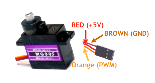
| Pin | Type | Description | Notes |
|---|---|---|---|
| GND | Power | Ground connection. Connect to ESP32 GND or external power supply ground. | Completes the electrical circuit. |
| +5V | Power | Power supply input (4.8V-6V). Can be powered from ESP32 5V pin for light loads. | Use external power supply for multiple servos or heavy loads. |
| DATA | PWM | PWM control signal. Pulse width: 1ms (0°), 1.5ms (90°), 2ms (180°). | Connect to a PWM-capable GPIO pin (e.g., GPIO 18). |
Operating voltage: 4.8V-6V
Torque: Up to 2.2 kg·cm at 4.8V
Angular range: 0° to 180°
Metal gears for better durability
Wiring the MG90S to ESP32
To control the MG90S servo with an ESP32, connect the brown wire to GND, red wire to 5V power, and orange wire to a PWM GPIO pin.
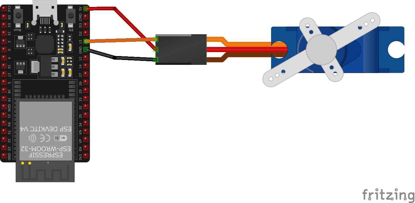
| MG90S pin | ESP32 pin | Purpose |
|---|---|---|
| GND (brown) | GND | Ground connection for both power and signal reference. |
| +5V (red) | 5V or External Supply | Power supply (4.8V-6V). Use external supply for multiple servos. |
| DATA (orange) | GPIO 18 | PWM control signal (50Hz, 1-2ms pulse width). |
PWM frequency: 50Hz (standard servo)
Current draw: ~100-500mA depending on load
For multiple servos, use external 5V power supply with shared GND
Add 100µF capacitor across power supply to reduce noise
MG90S code examples
// Requires library: "ESP32Servo"
#include <ESP32Servo.h> // The classic Arduino Servo library does not support the ESP32

Servo myServo; // Create a Servo object

void setup() {
  myServo.attach(18); // Servo signal on GPIO18, matches the wiring above
}

void loop() {
  myServo.write(0); // Move the servo to 0 degrees
  delay(1000);
  myServo.write(90); // Move the servo to 90 degrees
  delay(1000);
  myServo.write(180); // Move the servo to 180 degrees
  delay(1000);
}
On the ESP32 the classic Arduino Servo library does not work - install ESP32Servo instead, which provides the same familiar attach()/write() API on top of the ESP32's LEDC PWM hardware. The servo's signal wire connects to GPIO18 as shown above, and the sketch sweeps between 0, 90 and 180 degrees. Power the servo from 5V (or an external supply for stronger servos) - not from the 3.3V pin. The MG90S is the metal-gear sibling of the SG90 - same signal interface, slightly higher stall current, so prefer a dedicated 5V supply under load.
#include "driver/ledc.h"
#include "freertos/FreeRTOS.h"
#include "freertos/task.h"
#include "esp_err.h"

#define SERVO_PIN GPIO_NUM_18 // GPIO pin for the servo signal
#define SERVO_MIN_PULSEWIDTH 500 // Minimum pulse width in microseconds (0°)
#define SERVO_MAX_PULSEWIDTH 2500 // Maximum pulse width in microseconds (180°)
#define SERVO_MAX_DEGREE 180 // Maximum angle in degrees

// Convert an angle to an LEDC duty value: pulse width in us -> timer ticks
// (16-bit resolution at 50 Hz means the 20000 us period spans 65535 ticks)
uint32_t calculate_duty(uint32_t angle) {
    uint32_t pulse_us = SERVO_MIN_PULSEWIDTH + ((SERVO_MAX_PULSEWIDTH - SERVO_MIN_PULSEWIDTH) * angle) / SERVO_MAX_DEGREE;
    return (uint32_t)((uint64_t)pulse_us * 65535 / 20000);
}

void app_main() {
    // Configure the LEDC timer
    ledc_timer_config_t ledc_timer = {
        .speed_mode = LEDC_LOW_SPEED_MODE,
        .timer_num = LEDC_TIMER_0,
        .duty_resolution = LEDC_TIMER_16_BIT,
        .freq_hz = 50, // Frequency for servos
        .clk_cfg = LEDC_AUTO_CLK
    };
    ledc_timer_config(&ledc_timer);

    // Configure the LEDC channel
    ledc_channel_config_t ledc_channel = {
        .speed_mode = LEDC_LOW_SPEED_MODE,
        .channel = LEDC_CHANNEL_0,
        .timer_sel = LEDC_TIMER_0,
        .intr_type = LEDC_INTR_DISABLE,
        .gpio_num = SERVO_PIN,
        .duty = 0, // Initial duty cycle
        .hpoint = 0
    };
    ledc_channel_config(&ledc_channel);

    while (1) {
        // Move servo to 0°
        uint32_t duty = calculate_duty(0);
        ledc_set_duty(LEDC_LOW_SPEED_MODE, LEDC_CHANNEL_0, duty);
        ledc_update_duty(LEDC_LOW_SPEED_MODE, LEDC_CHANNEL_0);
        vTaskDelay(pdMS_TO_TICKS(1000));

        // Move servo to 90°
        duty = calculate_duty(90);
        ledc_set_duty(LEDC_LOW_SPEED_MODE, LEDC_CHANNEL_0, duty);
        ledc_update_duty(LEDC_LOW_SPEED_MODE, LEDC_CHANNEL_0);
        vTaskDelay(pdMS_TO_TICKS(1000));

        // Move servo to 180°
        duty = calculate_duty(180);
        ledc_set_duty(LEDC_LOW_SPEED_MODE, LEDC_CHANNEL_0, duty);
        ledc_update_duty(LEDC_LOW_SPEED_MODE, LEDC_CHANNEL_0);
        vTaskDelay(pdMS_TO_TICKS(1000));
    }
}
This code controls a servo using ESP-IDF's LEDC PWM driver. The calculate_pulse_width function computes the pulse width for a given angle (0° to 180°). The LEDC timer is set to 50 Hz, and the GPIO pin (e.g., GPIO_NUM_18) is configured as the output for the PWM signal. The servo's position is adjusted by updating the PWM duty cycle in the loop. The MG90S is the metal-gear sibling of the SG90 - same signal interface, slightly higher stall current, so prefer a dedicated 5V supply under load.
output:
  - platform: ledc
    id: pwm_output
    pin: GPIO18  # servo signal, matches the wiring above
    frequency: 50 Hz

servo:
  - id: my_servo
    output: pwm_output

number:
  - platform: template
    name: "MG90S Position"
    min_value: -100
    max_value: 100
    step: 1
    optimistic: true
    set_action:
      - servo.write:
          id: my_servo
          level: !lambda 'return x / 100.0;'
On the ESP32 the PWM output platform is ledc (the esp8266_pwm platform seen in older examples is ESP8266-only). The servo consumes the 50 Hz LEDC output on GPIO18, and the template number entity maps -100..100 to the servo range so you can slide it from Home Assistant; servo.write takes -1.0..1.0. The MG90S is the metal-gear sibling of the SG90 - same signal interface, slightly higher stall current, so prefer a dedicated 5V supply under load.
[env:esp32dev]
platform = espressif32
board = esp32dev
framework = arduino
monitor_speed = 115200
lib_deps =
madhephaestus/ESP32Servo @ ^3.0.5#include <Arduino.h>
#include <ESP32Servo.h> // The classic Arduino Servo library does not support the ESP32
Servo myServo; // Create a Servo object
void setup() {
myServo.attach(18); // Servo signal on GPIO18, matches the wiring above
}
void loop() {
myServo.write(0); // Move the servo to 0 degrees
delay(1000);
myServo.write(90); // Move the servo to 90 degrees
delay(1000);
myServo.write(180); // Move the servo to 180 degrees
delay(1000);
}This code demonstrates how to control a servo in PlatformIO using the Arduino framework. The servo is connected to GPIO 18, and its position is controlled using PWM signals generated by the myServo.attach() and myServo.write() methods. No additional libraries are needed as the Arduino Servo library is built into the framework. The setup() function initializes the servo, while the loop() moves it between 0°, 90°, and 180° with delays. The MG90S is the metal-gear sibling of the SG90 - same signal interface, slightly higher stall current, so prefer a dedicated 5V supply under load.
from machine import Pin, PWM
from time import sleep

# Configure PWM on GPIO18
servo = PWM(Pin(18))
servo.freq(50)  # Set frequency to 50 Hz

# Function to move the servo to a specific angle (0° to 180°)
def set_servo_angle(angle):
    # Convert angle to duty cycle (pulse width in microseconds)
    duty = int(40 + (angle / 180) * 115)  # Duty cycle range: 40-155 (approx. 500-2500 μs)
    servo.duty(duty)

# Main loop
while True:
    set_servo_angle(0)   # Move to 0°
    sleep(1)             # Wait 1 second
    set_servo_angle(90)  # Move to 90°
    sleep(1)             # Wait 1 second
    set_servo_angle(180) # Move to 180°
    sleep(1)             # Wait 1 second
This MicroPython code controls a servo motor using PWM on GPIO 18. The PWM object sets a 50 Hz frequency for the servo. The function set_servo_angle(angle) converts an angle (0° to 180°) into a duty cycle to position the servo. In the loop, the servo moves between 0°, 90°, and 180° with a 1-second delay between movements. The MG90S is the metal-gear sibling of the SG90 - same signal interface, slightly higher stall current, so prefer a dedicated 5V supply under load.
MG90S specifications
About the MG90S
The MG90S is the metal-gear sibling of TowerPro’s SG90: same footprint, same 4.8-6V supply range, same 50Hz PWM control signal, but a brass-and-aluminum gear train in place of the SG90’s plastic one. That swap is the whole point of the part - stall torque rises to about 1.8 kgf-cm at 4.8V and 2.2 kgf-cm at 6V, and metal gears shrug off the stripped-tooth failure mode that eventually kills a plastic-gear servo under repeated load. At 13.4g and roughly 23 x 12 x 31mm it is barely larger or heavier than the SG90 it replaces, so it drops into the same mounts and the same code.
As with the SG90, the MG90S name is heavily cloned, and there is no dependable way to confirm a given unit is a genuine TowerPro part from the outside - some informal indicators (a four-screw base and “TowerPro” molded into the case versus a two-screw unbranded case) get cited by hobbyists, but none of them are proof. Clones are common enough in this price bracket that it is worth treating any listed torque figure as optimistic until a project’s own load testing says otherwise.
Wiring and firmware are identical to the SG90: a 3-wire connector (ground, +5V, PWM signal), and the same ESP32Servo-based code covered on the general PWM servo page. For loads the MG90S still cannot handle, the larger MG996R steps up to standard servo size and considerably more torque; our ESP32 servo guide compares all three side by side.
MG90S troubleshooting
Servo Rotates Continuously Instead of Moving to Position
›
Issue: The MG90S servo rotates 360 degrees continuously rather than moving to a specified position.
Possible causes include using a continuous rotation version of the servo or incorrect pulse width modulation (PWM) signals.
Solution: Verify whether the servo is a standard positional model or a continuous rotation variant. Standard MG90S servos are designed for approximately 180-degree rotation. If the servo rotates continuously, it may be a continuous rotation model, which interprets PWM signals differently. Ensure that the PWM signals correspond to the servo's specifications, typically with pulse widths between 1ms and 2ms for standard servos.
›
Issue: The MG90S servo does not achieve its full expected rotation range, moving less than 180 degrees.
Possible causes include incorrect PWM signal parameters or mechanical limitations.
Solution: Adjust the PWM signal to ensure it falls within the servo's required pulse width range. For the MG90S, pulse widths typically range from 0.8ms to 2.1ms to achieve the full rotation. Verify that there are no mechanical obstructions preventing movement.
Limited Rotation Range
›
Servo Jittering or Twitching
Issue: The MG90S servo exhibits jittery or twitchy movements during operation.
Possible causes include electrical noise, insufficient power supply, or signal interference.
Solution: Ensure a stable and adequate power supply to the servo, as voltage fluctuations can cause erratic behavior. Implement proper grounding and consider adding decoupling capacitors to filter out electrical noise. Check for any sources of signal interference and ensure that control signals are clean and within the appropriate voltage levels.
Servo Not Responding to Control Signals
›
Issue: The MG90S servo does not respond to input control signals, remaining stationary.
Possible causes include incorrect wiring, faulty connections, or incompatible signal voltage levels.
Solution: Double-check all wiring connections to ensure they are correct and secure. Verify that the control signal wire is connected to a PWM-capable pin on the microcontroller. Ensure that the signal voltage levels are compatible with the servo's requirements, typically 3.3V or 5V depending on the microcontroller and servo specifications.
Where to buy the MG90S

Resources
Similar sensors


