
General Servo
<p>PWM servos are controlled using Pulse Width Modulation signals to adjust their position or speed. They are widely used in robotics, RC models, and electronics projects. For detailed specifications and code examples, refer to the specific servo pages such as SG90, MG90S, and MG996R.</p>

General Servo pinout
General PWM servos have 3 wires: GND (brown/black), VCC (red), and DATA/Signal (orange/yellow/white).
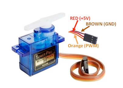
| Pin | Type | Description | Notes |
|---|---|---|---|
| GND | Power | Ground connection. Connect to microcontroller GND and/or external power supply ground. | Completes the electrical circuit. |
| VCC | Power | Power supply input (typically 4.8V-6V). Voltage varies by servo model - check datasheet. | Use external power supply for multiple servos or high-torque models. |
| DATA/Signal | PWM | PWM control signal. Pulse width: 1ms (0°), 1.5ms (90°), 2ms (180°). | Connect to a PWM-capable GPIO pin on the microcontroller. |
Wire colors may vary by manufacturer (orange/yellow/white for signal)
Typical operating voltage: 4.8V-6V (verify with specific servo datasheet)
Angular range: typically 0° to 180° (some servos have different ranges)
PWM frequency: 50Hz (standard for hobby servos)
Pulse width timing may need adjustment for specific servo models
Wiring the General Servo to ESP32
To control a PWM servo with a microcontroller, connect GND (brown/black) to ground, VCC (red) to appropriate power supply, and DATA (orange/yellow/white) to a PWM GPIO pin.
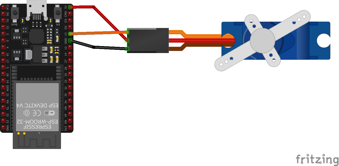
| General Servo pin | ESP32 pin | Purpose |
|---|---|---|
| GND (brown/black) | GND | Ground connection for both power and signal reference. |
| VCC (red) | 5V or External Supply | Power supply. Use external supply for multiple servos or high-current models. |
| DATA (orange/yellow/white) | GPIO 18 | PWM control signal (50Hz, 1-2ms pulse width). |
PWM frequency: 50Hz (standard hobby servo frequency)
For single small servo (SG90): ESP32 5V pin can power it
For multiple servos or high-torque models: use external 5-6V power supply
Always connect all grounds together (ESP32 + power supply + servo)
Add 100µF-470µF capacitor across power supply for noise reduction
Pulse width timing: 1ms=0°, 1.5ms=90°, 2ms=180° (may vary by model)
Use ESP32Servo library or LEDC for PWM control
Specific servo pages: SG90 (lightweight), MG90S (metal gears), MG996R (high torque)
General Servo code examples
// Requires library: "ESP32Servo"
#include <ESP32Servo.h> // The classic Arduino Servo library does not support the ESP32

Servo myServo; // Create a Servo object

void setup() {
  myServo.attach(18); // Servo signal on GPIO18, matches the wiring above
}

void loop() {
  myServo.write(0); // Move the servo to 0 degrees
  delay(1000);
  myServo.write(90); // Move the servo to 90 degrees
  delay(1000);
  myServo.write(180); // Move the servo to 180 degrees
  delay(1000);
}
On the ESP32 the classic Arduino Servo library does not work - install ESP32Servo instead, which provides the same familiar attach()/write() API on top of the ESP32's LEDC PWM hardware. The servo's signal wire connects to GPIO18 as shown above, and the sketch sweeps between 0, 90 and 180 degrees. Power the servo from 5V (or an external supply for stronger servos) - not from the 3.3V pin.
#include "driver/ledc.h"
#include "freertos/FreeRTOS.h"
#include "freertos/task.h"
#include "esp_err.h"

#define SERVO_PIN GPIO_NUM_18 // GPIO pin for the servo signal
#define SERVO_MIN_PULSEWIDTH 500 // Minimum pulse width in microseconds (0°)
#define SERVO_MAX_PULSEWIDTH 2500 // Maximum pulse width in microseconds (180°)
#define SERVO_MAX_DEGREE 180 // Maximum angle in degrees

// Convert an angle to an LEDC duty value: pulse width in us -> timer ticks
// (16-bit resolution at 50 Hz means the 20000 us period spans 65535 ticks)
uint32_t calculate_duty(uint32_t angle) {
    uint32_t pulse_us = SERVO_MIN_PULSEWIDTH + ((SERVO_MAX_PULSEWIDTH - SERVO_MIN_PULSEWIDTH) * angle) / SERVO_MAX_DEGREE;
    return (uint32_t)((uint64_t)pulse_us * 65535 / 20000);
}

void app_main() {
    // Configure the LEDC timer
    ledc_timer_config_t ledc_timer = {
        .speed_mode = LEDC_LOW_SPEED_MODE,
        .timer_num = LEDC_TIMER_0,
        .duty_resolution = LEDC_TIMER_16_BIT,
        .freq_hz = 50, // Frequency for servos
        .clk_cfg = LEDC_AUTO_CLK
    };
    ledc_timer_config(&ledc_timer);

    // Configure the LEDC channel
    ledc_channel_config_t ledc_channel = {
        .speed_mode = LEDC_LOW_SPEED_MODE,
        .channel = LEDC_CHANNEL_0,
        .timer_sel = LEDC_TIMER_0,
        .intr_type = LEDC_INTR_DISABLE,
        .gpio_num = SERVO_PIN,
        .duty = 0, // Initial duty cycle
        .hpoint = 0
    };
    ledc_channel_config(&ledc_channel);

    while (1) {
        // Move servo to 0°
        uint32_t duty = calculate_duty(0);
        ledc_set_duty(LEDC_LOW_SPEED_MODE, LEDC_CHANNEL_0, duty);
        ledc_update_duty(LEDC_LOW_SPEED_MODE, LEDC_CHANNEL_0);
        vTaskDelay(pdMS_TO_TICKS(1000));

        // Move servo to 90°
        duty = calculate_duty(90);
        ledc_set_duty(LEDC_LOW_SPEED_MODE, LEDC_CHANNEL_0, duty);
        ledc_update_duty(LEDC_LOW_SPEED_MODE, LEDC_CHANNEL_0);
        vTaskDelay(pdMS_TO_TICKS(1000));

        // Move servo to 180°
        duty = calculate_duty(180);
        ledc_set_duty(LEDC_LOW_SPEED_MODE, LEDC_CHANNEL_0, duty);
        ledc_update_duty(LEDC_LOW_SPEED_MODE, LEDC_CHANNEL_0);
        vTaskDelay(pdMS_TO_TICKS(1000));
    }
}
This code controls a servo using ESP-IDF's LEDC PWM driver. The calculate_pulse_width function computes the pulse width for a given angle (0° to 180°). The LEDC timer is set to 50 Hz, and the GPIO pin (e.g., GPIO_NUM_18) is configured as the output for the PWM signal. The servo's position is adjusted by updating the PWM duty cycle in the loop.
output:
  - platform: ledc
    id: pwm_output
    pin: GPIO18  # servo signal, matches the wiring above
    frequency: 50 Hz

servo:
  - id: my_servo
    output: pwm_output

number:
  - platform: template
    name: "Servo Position"
    min_value: -100
    max_value: 100
    step: 1
    optimistic: true
    set_action:
      - servo.write:
          id: my_servo
          level: !lambda 'return x / 100.0;'
On the ESP32 the PWM output platform is ledc (the esp8266_pwm platform seen in older examples is ESP8266-only). The servo consumes the 50 Hz LEDC output on GPIO18, and the template number entity maps -100..100 to the servo range so you can slide it from Home Assistant; servo.write takes -1.0..1.0.
[env:esp32dev]
platform = espressif32
board = esp32dev
framework = arduino
monitor_speed = 115200
lib_deps =
madhephaestus/ESP32Servo @ ^3.0.5#include <Arduino.h>
#include <ESP32Servo.h> // The classic Arduino Servo library does not support the ESP32
Servo myServo; // Create a Servo object
void setup() {
myServo.attach(18); // Servo signal on GPIO18, matches the wiring above
}
void loop() {
myServo.write(0); // Move the servo to 0 degrees
delay(1000);
myServo.write(90); // Move the servo to 90 degrees
delay(1000);
myServo.write(180); // Move the servo to 180 degrees
delay(1000);
}This code demonstrates how to control a servo in PlatformIO using the Arduino framework. The servo is connected to GPIO 18, and its position is controlled using PWM signals generated by the myServo.attach() and myServo.write() methods. No additional libraries are needed as the Arduino Servo library is built into the framework. The setup() function initializes the servo, while the loop() moves it between 0°, 90°, and 180° with delays.
from machine import Pin, PWM
from time import sleep

# Configure PWM on GPIO18
servo = PWM(Pin(18))
servo.freq(50)  # Set frequency to 50 Hz

# Function to move the servo to a specific angle (0° to 180°)
def set_servo_angle(angle):
    # Convert angle to duty cycle (pulse width in microseconds)
    duty = int(40 + (angle / 180) * 115)  # Duty cycle range: 40-155 (approx. 500-2500 μs)
    servo.duty(duty)

# Main loop
while True:
    set_servo_angle(0)   # Move to 0°
    sleep(1)             # Wait 1 second
    set_servo_angle(90)  # Move to 90°
    sleep(1)             # Wait 1 second
    set_servo_angle(180) # Move to 180°
    sleep(1)             # Wait 1 second
This MicroPython code controls a servo motor using PWM on GPIO 18. The PWM object sets a 50 Hz frequency for the servo. The function set_servo_angle(angle) converts an angle (0° to 180°) into a duty cycle to position the servo. In the loop, the servo moves between 0°, 90°, and 180° with a 1-second delay between movements.
About the General Servo
A hobby servo like the ones on this site is not just a motor - inside the case it packs a small DC motor, a reduction gearbox, a position-feedback potentiometer, and the control electronics that compare the two and drive the motor to match. All of that is controlled with a single PWM wire: a pulse repeated at 50Hz, whose width tells the servo where to point. The de facto standard is 1000-2000us for the two end stops with 1500us as center, though the full mechanical range on most micro servos - the SG90, MG90S, and MG996R covered on this site - extends closer to 500-2500us before it hits a physical stop or stalls trying.
On the ESP32 this needs a library built for the chip’s own PWM hardware, not the stock Arduino Servo library. That library was written around AVR’s 16-bit hardware timers and does not target the ESP32’s LEDC peripheral (or MCPWM on the S3), so the community-maintained ESP32Servo library (installable from the Arduino Library Manager) is the one that actually works, exposing the same familiar attach()/write() calls while mapping them onto LEDC PWM channels underneath.
Power is the other thing worth getting right before wiring anything up: a small servo can pull a stall current spike well past 200 mA the instant it meets resistance, and pulling that from the ESP32 board’s onboard 5V regulator alongside the MCU itself is a common cause of brownout resets. Give servos - especially more than one, or anything driven through a PCA9685 PWM controller - their own 5V supply with a ground wire tied back to the ESP32, and keep the signal wire separate from the power wiring.
Where to buy the General Servo

Similar sensors


