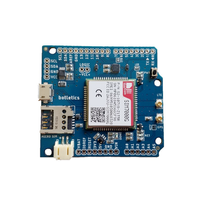
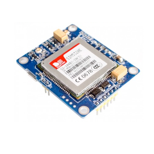
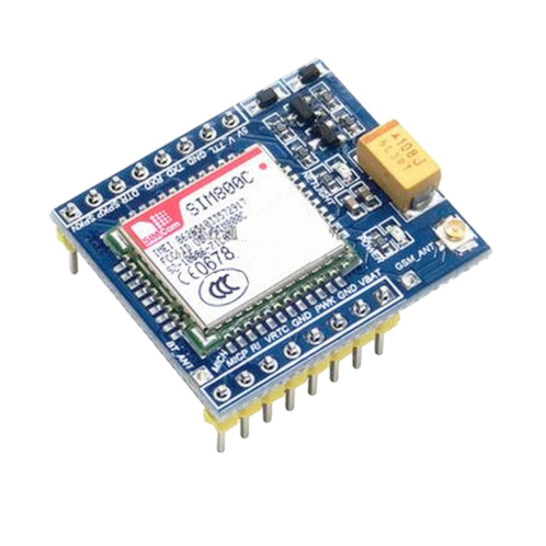
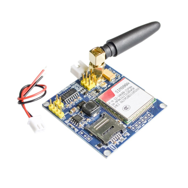
ESP32 SIM7000 LTE CAT-M1/NB-IoT Module
Overview
The SIM7000 is a versatile LTE CAT-M1/NB-IoT module that provides reliable communication capabilities for various IoT applications. Its compact design, low power consumption, and multiple interfaces make it an ideal choice for projects requiring cellular connectivity.
About SIM7000 LTE CAT-M1/NB-IoT Module
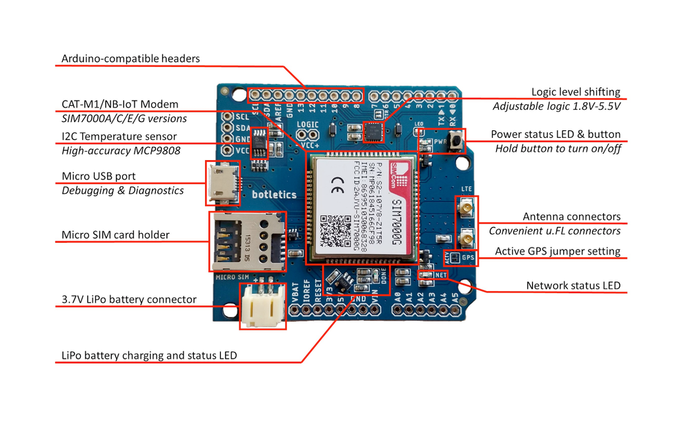
The SIM7000 is a multi-band LTE-FDD and dual-band GPRS/EDGE module designed for low-power IoT applications. It supports LTE CAT-M1, LTE CAT-NB1 (NB-IoT), and GPRS/EDGE, making it a versatile solution for modern cellular communication needs. Its compact size and pin compatibility with SIM900 and SIM800 series make it an excellent choice for upgrading existing designs.
⚡ Key Features
- Multi-Network Support – Works with LTE CAT-M1, NB-IoT (CAT-NB1), and GPRS/EDGE.
- Low Power Consumption – Optimized for battery-powered IoT applications.
- Backward Compatibility – Pin-compatible with SIM900 and SIM800 series for easy upgrades.
- Flexible Connectivity – Ideal for smart meters, asset tracking, and remote monitoring.
🔗 Still choosing a SIM module? Check the ESP32 SIM Modules Comparison Table for a breakdown of LTE, 3G, and GPRS options. 🚀
Where to Buy


Prices are subject to change. We earn from qualifying purchases as an Amazon Associate.
Technical Specifications
Pinout Configuration
The VCC pin is used to supply power to the sensor, and it typically requires 3.3V or 5V (refer to the datasheet for specific voltage requirements). The GND pin is the ground connection and must be connected to the ground of your ESP32.
The SIM7000 pinout includes:
- VBAT: Power supply input (3.0V to 4.3V).
- GND: Ground connection.
- TXD: UART Transmit Data (connects to microcontroller RX).
- RXD: UART Receive Data (connects to microcontroller TX).
- PWRKEY: Power on/off control (active low).
- NETLIGHT: Network status indication.
- STATUS: Module operating status indication.
- ANT_MAIN: Main antenna connection for LTE/GPRS.
- ANT_GNSS: Antenna connection for GNSS.
- SIM_VDD: SIM card power supply.
- SIM_DATA: SIM card data I/O.
- SIM_CLK: SIM card clock.
- SIM_RST: SIM card reset.
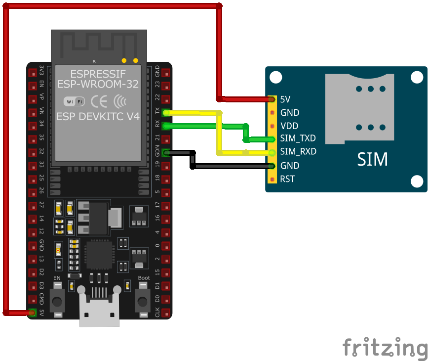
Wiring with ESP32
- Connect
VBATto a stable power supply within the range of 3.0V to 4.3V. - Connect
GNDto the system ground. - Connect
TXDto the microcontroller's RX pin. - Connect
RXDto the microcontroller's TX pin. - Control the
PWRKEYpin to power the module on or off (active low). - Connect the
ANT_MAINto a suitable LTE/GPRS antenna for network connectivity. - Optionally, connect the
ANT_GNSSto a GNSS antenna for location services. - Connect the SIM card interface pins (
SIM_VDD,SIM_DATA,SIM_CLK,SIM_RST) to a SIM card holder as per the hardware design guidelines.
Troubleshooting Guide
Common Issues
❌ Module Fails to Power On
Issue: The SIM7000 module does not power up or respond to commands.
Possible causes include insufficient power supply, incorrect wiring, or faulty hardware.
Solution: Ensure the module is connected to a stable power source within the recommended voltage range of 3.0V to 4.3V. Verify that all connections are secure and correctly configured. If the problem persists, consider testing the module with a different power source or replacing it.
📱 SIM Card Not Recognized
Issue: The module fails to detect or register the SIM card.
Possible causes include improper SIM card insertion, unsupported SIM card type, or SIM card lock.
Solution: Ensure the SIM card is properly inserted into the module's SIM card slot and is compatible with the GSM network. Verify that the SIM card is active and unlocked. If necessary, test the SIM card in another device to confirm its functionality.
⚠️ Poor Network Signal or Connectivity Issues
Issue: The module experiences weak signal strength or fails to maintain a stable network connection.
Possible causes include improper antenna connection, environmental interference, or network coverage limitations.
Solution: Ensure the GSM antenna is securely connected to the module and positioned for optimal signal reception. Avoid placing the module near sources of electromagnetic interference. Check the network coverage in your area to ensure adequate signal strength.
💬 AT Commands Not Responding
Issue: The module does not respond to AT commands sent from the microcontroller or computer.
Possible causes include incorrect baud rate settings, faulty serial connections, or improper command syntax.
Solution: Verify that the baud rate of the module matches that of the microcontroller or computer; the default baud rate is 115200 bps. Check that the TX and RX lines are correctly connected and that there are no loose connections. Ensure that AT commands are correctly formatted and terminated with a carriage return.
🌍 GPS Functionality Not Working
Issue: The SIM7000 module fails to acquire GPS signals or provide location data.
Possible causes include improper antenna connection, obstructed view of the sky, or GPS functionality not enabled.
Solution: Ensure the GPS antenna is properly connected and has a clear view of the sky to receive satellite signals. Verify that the GPS functionality is enabled by sending the appropriate AT commands to power on the GPS engine.
Debugging Tips
🔍 Serial Monitor
Use the Serial Monitor to check for error messages and verify the sensor's output. Add debug prints in your code to track the sensor's state.
⚡ Voltage Checks
Use a multimeter to verify voltage levels and check for continuity in your connections. Ensure the power supply is stable and within the sensor's requirements.
Additional Resources
Code Examples
Arduino Example
#include <SoftwareSerial.h>

SoftwareSerial sim7000(10, 11); // RX, TX
#define PWRKEY 9

void powerOnSIM7000() {
    pinMode(PWRKEY, OUTPUT);
    digitalWrite(PWRKEY, LOW);
    delay(1000); // Hold PWRKEY low for 1 second
    digitalWrite(PWRKEY, HIGH);
    delay(5000); // Wait for the module to initialize
}

void setup() {
    Serial.begin(9600);
    sim7000.begin(9600);
    powerOnSIM7000();

    // Test AT command
    sim7000.println("AT");
    delay(1000);
    while (sim7000.available()) {
        Serial.write(sim7000.read());
    }

    // Set SMS text mode
    sim7000.println("AT+CMGF=1");
    delay(1000);
    while (sim7000.available()) {
        Serial.write(sim7000.read());
    }

    // Send SMS
    sim7000.println("AT+CMGS="+1234567890""); // Replace with recipient's number
    delay(1000);
    sim7000.print("Hello from SIM7000");
    sim7000.write(26); // CTRL+Z to send
    delay(5000);
    while (sim7000.available()) {
        Serial.write(sim7000.read());
    }
}

void loop() {
    // Add code to handle incoming messages or other functionalities
}ESP-IDF Example
#include <stdio.h>
#include "driver/uart.h"
#include "driver/gpio.h"
#include "freertos/task.h"

#define TX_PIN 17
#define RX_PIN 16
#define PWRKEY_PIN 4
#define UART_PORT UART_NUM_1

void init_uart() {
    uart_config_t uart_config = {
        .baud_rate = 9600,
        .data_bits = UART_DATA_8_BITS,
        .parity = UART_PARITY_DISABLE,
        .stop_bits = UART_STOP_BITS_1,
        .flow_ctrl = UART_HW_FLOWCTRL_DISABLE
    };

    uart_param_config(UART_PORT, &uart_config);
    uart_set_pin(UART_PORT, TX_PIN, RX_PIN, UART_PIN_NO_CHANGE, UART_PIN_NO_CHANGE);
    uart_driver_install(UART_PORT, 1024, 0, 0, NULL, 0);
}

void power_on_sim7000() {
    gpio_set_direction(PWRKEY_PIN, GPIO_MODE_OUTPUT);
    gpio_set_level(PWRKEY_PIN, 0);
    vTaskDelay(1000 / portTICK_PERIOD_MS); // Hold PWRKEY low for 1 second
    gpio_set_level(PWRKEY_PIN, 1);
    vTaskDelay(5000 / portTICK_PERIOD_MS); // Wait for the module to initialize
}

void app_main(void) {
    init_uart();
    power_on_sim7000();

    char *test_cmd = "AT\r\n";
    uart_write_bytes(UART_PORT, test_cmd, strlen(test_cmd));

    while (true) {
        char data[128];
        int len = uart_read_bytes(UART_PORT, data, sizeof(data), 100 / portTICK_PERIOD_MS);
        if (len > 0) {
            data[len] = '\0';
            printf("Response: %s\n", data);
        }
        vTaskDelay(1000 / portTICK_PERIOD_MS);
    }
}ESPHome Example
uart:
  tx_pin: GPIO17
  rx_pin: GPIO16
  baud_rate: 9600

switch:
  - platform: gpio
    name: "SIM7000 Power"
    pin:
      number: GPIO4
      inverted: true

switch:
  - platform: template
    name: "Send AT Command"
    turn_on_action:
      - uart.write: "AT\r\n"

sensor:
  - platform: custom
    lambda: |-
      return {nullptr};
    sensors:
- name: "SIM7000 Response"PlatformIO Example
platformio.ini
[env:sim7000]
platform = espressif32
board = esp32dev
framework = arduino
monitor_speed = 115200
PlatformIO Example Code
#include <HardwareSerial.h>
#include <Arduino.h>

HardwareSerial sim7000(1);
#define PWRKEY 4

void power_on_sim7000() {
    pinMode(PWRKEY, OUTPUT);
    digitalWrite(PWRKEY, LOW);
    delay(1000); // Hold PWRKEY low for 1 second
    digitalWrite(PWRKEY, HIGH);
    delay(5000); // Wait for initialization
}

void setup() {
    Serial.begin(115200);
    sim7000.begin(9600, SERIAL_8N1, 16, 17); // RX, TX
    power_on_sim7000();

    // Test AT command
    sim7000.println("AT");
    delay(1000);
    while (sim7000.available()) {
        Serial.write(sim7000.read());
    }

    // Send SMS
    sim7000.println("AT+CMGF=1"); // Set SMS to text mode
    delay(1000);
    sim7000.println("AT+CMGS="+1234567890""); // Replace with recipient's number
    delay(1000);
    sim7000.print("Hello from SIM7000");
    sim7000.write(26); // CTRL+Z to send SMS
    delay(5000);
}

void loop() {
    // Handle incoming data or other functionalities
}power_on_sim7000 function toggles the PWRKEY pin (GPIO4) to activate the module. The AT command is sent to test communication, and SMS functionality is implemented in the setup. Additional functionalities, like GNSS data retrieval or GPRS communication, can be added in the loop.MicroPython Example
from machine import UART, Pin
import time

# Initialize UART
uart = UART(2, baudrate=9600, tx=17, rx=16)
pwrkey = Pin(4, Pin.OUT)

def power_on_sim7000():
    pwrkey.value(0)
    time.sleep(1)  # Hold PWRKEY low for 1 second
    pwrkey.value(1)
    time.sleep(5)  # Wait for module to initialize

def send_at(command):
    uart.write(command + '\r\n')
    time.sleep(1)
    while uart.any():
        print(uart.read().decode('utf-8'), end='')

# Power on the module
power_on_sim7000()

# Test communication
send_at('AT')

# Send SMS
send_at('AT+CMGF=1')  # Set SMS to text mode
send_at('AT+CMGS="+1234567890"')  # Replace with recipient's number
uart.write("Hello from MicroPython" + chr(26))power_on_sim7000 function activates the module using the PWRKEY pin (GPIO4). The send_at function sends AT commands and prints the responses. The script initializes the module, tests communication, and demonstrates how to send an SMS. Additional logic for handling GNSS data or GPRS communication can be added.Conclusion
The ESP32 SIM7000 LTE CAT-M1/NB-IoT Module is a powerful SIM sensor that offers excellent performance and reliability. With support for multiple development platforms including Arduino, ESP-IDF, ESPHome, PlatformIO, and MicroPython, it's a versatile choice for your IoT projects.
For optimal performance, ensure proper wiring and follow the recommended configuration for your chosen development platform.
Always verify power supply requirements and pin connections before powering up your project to avoid potential damage.
