

Reverse-engineering the ScreenBar Halo remote with a bare ESP32-S3
How a bare ESP32-S3 learned to hear a 2.4 GHz remote: raw I/Q, a GFSK demodulator in C, the ADC's ring mode and a gate that keeps Wi-Fi out.
I wanted my first-gen ScreenBar Halo in Home Assistant, running on one cheap ESP32-S3 and nothing else. So I taught a bare S3 to sniff the remote. It finds the lamp's address by itself, with no CC2500 or second radio, and it listens 99.7% of the time on a crowded 2.4 GHz band, so Home Assistant follows every turn of the dial. That listener is the radio in my Home Assistant bridge for the Halo. That post is the build guide; this one is how it works, from raw I/Q samples (the radio signal as pairs of numbers) to a listener that never stops.
I didn't start from zero. Through the BenQ ScreenBar thread on the Home Assistant forum I found Djoko-cli, who had decoded the radio protocol, and Junyi-99, whose firmware already had a bare ESP32-S3 sending packets to the lamp. That firmware switched the receiver on for about a millisecond after each command, just to check the lamp's ACK, and finding your lamp's 4-byte address still took a second radio. Keeping that receiver on, and making it hear the remote, is the part I built.
This drives the S3's radio through undocumented parts of the chip. The S3 radio code this builds on says it is not meant or qualified for real products, and that its signals may not meet your local radio rules. It also says it may permanently change the radio's analog behaviour, which rules the board out of any certified product later. Use a board you can dedicate to it, keep the transmit power low, only talk to your own lamp, and don't build these to sell.
Not affiliated with or endorsed by BenQ. BenQ and ScreenBar are trademarks of BenQ Corporation, used here only to name the product.
What's new here
The protocol and the S3 radio came from others (credits at the end). This is what I added on top:
1Why the usual tools don't work
The Halo link is slow and narrow, which sounds easy, but it falls into a gap between the cheap tools.
Common tuners stop around 1.7 GHz. 2405 MHz needs a downconverter in front.
Can't reach itSame ESB-style framing, and the promiscuous-mode trick is famous. But its slowest rate is 250 kbit/s, and this link runs at 125.
Wrong bit rateCan be set to 125 kbit/s GFSK. That's how the address was first found, from a raw capture.
Works, extra moduleHoltek's module with the lamp's own BC5602 chip. Talks to the lamp natively once you know the address, but can't discover it.
Not for finding itReal SDRs that cover 2.4 GHz. Overkill for one address.
Works, costs moreAlready has a 2.4 GHz receiver with an ADC behind it. The catch: it takes undocumented chip internals, and Wi-Fi is off while it listens.
This post2What the remote sends
The remote and lamp use Enhanced ShockBurst-style frames, the format Nordic's nRF24 chips made common, on 2405 MHz: GFSK at 125 kbit/s with +/-160 kHz deviation. I checked every field below against my own captures.
A few rules matter for listening. Each remote/lamp pair has its own address, set at pairing. The ACK is empty, so the lamp never reports its state; you only learn it by hearing what the remote says. Buttons send each state 3 times about 100 ms apart, and the dial sends a frame every ~112 ms while it turns. Every state frame is absolute, so a lost one never leaves the lamp half-updated.
The payload is two bytes: flags, then a value. These six cover most of what the remote sends:
C5 A5flags set: Power, Front, Bright, Back.On, both lights, brightness 50% A5 on the remote's 4C-FE scaleC3 35flags set: Power, Front, Colour, Back.On, both lights, colour 35 00 is coldest, 64 warmest45 4Cflags set: Front, Bright, Back.Off The light bits stay set, so power brings the same lights backC9 00flags set: Power, Front, Heart, Back.Heart (favourite) Afterwards the bridge marks brightness and colour as unknownE1 01flags set: Power, Front, Auto, Back.Auto button Starts auto mode. I caught one press, and it carried 01FF 00flags set: Power, Front, Auto, Stream?, Heart, Bright, Colour, Back.Wake-up The remote waking up; it carries no state3Turning a Wi-Fi radio into an SDR
The raw sample access isn't mine (see Credits). An undocumented debug path lets the CPU read I/Q samples straight from the radio, and a port for the S3 adds playback through the transmitter. The firmware I started from builds each Halo packet on the S3 itself, plays it, then captures the lamp's ACK.
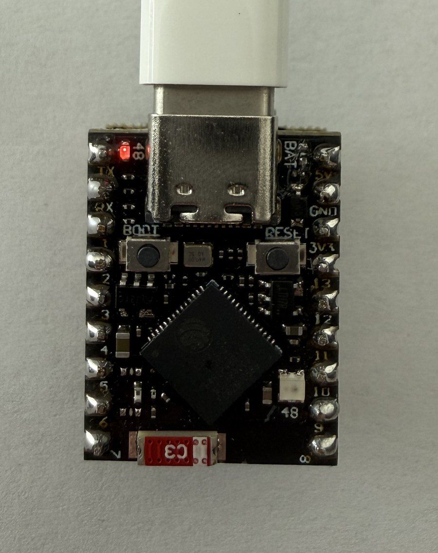
What the S3 gives you
- Receive
- 10-bit I/Q at 16 MS/s
- One capture
- 16,380 samples in a 64 KB bank, just over 1 ms
- Transmit
- The DAC plays 40 MS/s from banks you fill
- Tuning
- Locked to Wi-Fi channel 1 (2412 MHz), then shifted -7 MHz to 2405
- The cost
- Wi-Fi is off while it runs, and it needs one pinned ESP-IDF build
Everything between the samples and the bits is plain C. For the bridge I rewrote that part so it also runs on a PC, where the tests feed it simulated frames. Here is a real dial frame going through it:
4Listening without sending
The firmware already captured about 1 ms after each command to look for the ACK. My first change was a SNIFF command: the same capture with the transmitter off, decoding every frame from any address and keeping the ones whose CRC checks out. The first real run, turning the dial and pressing buttons for two minutes:
Listening for 120 s. Turn the remote dial and press its buttons NOW.
  CMD 1A2B3C4D  pid 1  payload FF00  offset -15 kHz  t=66.1s
  CMD 1A2B3C4D  pid 2  payload C5DF  offset -26 kHz  t=68.5s
  CMD 1A2B3C4D  pid 1  payload C5FB  offset -11 kHz  t=74.0s
  ACK 1A2B3C4D  pid 1  payload 0000  offset -23 kHz  t=100.7s
  CMD 1A2B3C4D  pid 2  payload C596  offset -22 kHz  t=102.3s
  CMD 1A2B3C4D  pid 1  payload C336  offset -16 kHz  t=109.9s
6 frame(s) in 14881 capture(s), 0 RX error(s).
Your lamp address is almost certainly 1A2B3C4D.
That found the address. But the board spent most of its time decoding, and a faster decoder alone wouldn't have been enough. Even with no gap between captures, a 648 us command only fits inside a 1,024 us window if it starts in the first 376 us:
With the remote's 3 repeats, a press gets through about 75% of the time at best, even with no gaps between captures. The S3 had to listen continuously.
5Listening without gaps
The firmware I started from used one-shot captures. Its transmit side already switches DAC banks mid-playback, so I probed whether the receive side could do the same: fill the banks with 0xFFFFFFFF (the ADC writes only 20 bits per sample), capture, and look at what got overwritten.
- A normal capture is one-shot. DONE fires at 1,024 us for 16,380 samples, and nothing is written after, even if you hand the ADC another bank.
- The length field is 14 bits. Asking for 49,140 samples behaves like 16,372.
- Bit 14 of
ADC_CTRL(0x60033d5c) makes it a ring. DONE never comes and the ADC keeps writing until stopped. It wraps after the full 64 KB bank, 16,384 words, so exactly every 1,024 us. - Swapping the bank owner mid-capture works. Writes continue in the other bank at the same offset.
I found that the hard way, then learned it was already written down: esp-sdr calls it circular mode and uses it for continuous capture on the S3, and esp-sdr-zephyr describes the same ring and the bank switching in its hardware notes. What follows is how the bridge uses it.
Two banks make a double buffer. Core 1 flips the bank owner by cycle count every 1,024 us, so every flip lands at the same offset. It also sums each finished bank into blocks, 620-632 us of every lap. Core 0 runs the gate and the demodulator, carrying the previous bank's tail across, so a frame that straddles the flip is still read in one piece. The flip itself is a busy-wait on the cycle counter:
#define ADC_MODE_RING   (1u << 14)   /* never DONE; the write address wraps every 16384 words */

bool phy_s3_ring_next(phy_s3_ring_t *ring, phy_s3_chunk_t *chunk)
{
    uint32_t at = ring->next;
    while ((int32_t)(at - esp_cpu_get_cycle_count()) > (int32_t)MASKED_CYCLES) {
    }
    portENTER_CRITICAL(&phy_s3_mux);
    /* Even a few cycles late would move the flip off its offset, so give up instead. */
    bool late = (int32_t)(at - esp_cpu_get_cycle_count()) <= 0;
    while ((int32_t)(at - esp_cpu_get_cycle_count()) > 0) {
    }
    if (!late) {
        REG_WRITE(SRAM_OWNER_REG, owner(ring->bank ^ 1u));
    }
portEXIT_CRITICAL(&phy_s3_mux);The proof was frames that cross the seam. In 3 minutes of dial and power presses the S3 heard 375 frames, 165 of them the lamp's ACKs. 228 of them (61%) spanned a bank flip and still passed CRC, close to the ~58% their lengths predict. A lost sample or a slipped offset at the seam would have broken them. There were 0 late flips.
62405 MHz is crowded
With nonstop capture the next problem was everything else on the air. Wi-Fi channel 1 covers 2401-2423 MHz, right over the Halo's carrier. With a plain energy gate (2x the noise floor), 20-26% of 32 us segments on my desk were loud, including ~50 bursts a second longer than 1 ms. Demodulating all of it took 60-80% of core 0 and still dropped ~150 windows a second.
The fix was to measure how narrowband a segment is, not how loud. Take the lag-1 correlation of the block sums over their power, a 0-1 score for how steadily each sample turns from the one before. A Halo frame is a single tone wandering +/-160 kHz, so it scores high, while wideband traffic like Wi-Fi scores low. On my desk, with the remote untouched, 98% of loud segments scored under 0.3. Turning the dial added about 202 segments a second between 0.8 and 1.0, where the background puts 4. A segment only opens a demod window if all three hold:
One more class got through: narrowband senders off our carrier. Logging the mean frequency of every window-opening run showed ~1,650 of ~1,720 frame-sized runs sitting at -950 to -850 kHz. My guess is Bluetooth advertising on 2402 MHz, folded to about -1 MHz by the 8x decimation. A Halo frame can't sit further out than the detector's 200 kHz offset range plus the 160 kHz deviation, 360 kHz, so with a little margin the gate drops anything centred more than 380 kHz away. Windows went from ~47 a second to 0.04, with 0 drops, and core 0 settled at about 15%.
The ring isn't Halo-specific, and the gate's idea carries over to other slow, narrow signals near 2.4 GHz. Its thresholds, the demodulator and the detector are tuned for this one link, though.
7What the captures taught me about the lamp
Before the bridge existed, I ran a guided session on the first SNIFF build: press one thing, see what comes out. At 12% listening it missed some presses (the front/back button and power-off never showed up), but it caught these:
A few more things I checked:
80 | 02 | lights with a value from 00 (cold) to 64 (warm), the range halo-nrf52840 and the protocol notes use. I added it to the S3 firmware as its own command and tested cold, mid and warm.8From a sniffer to a bridge
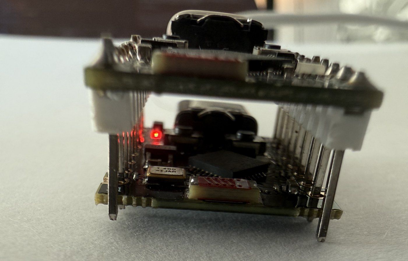
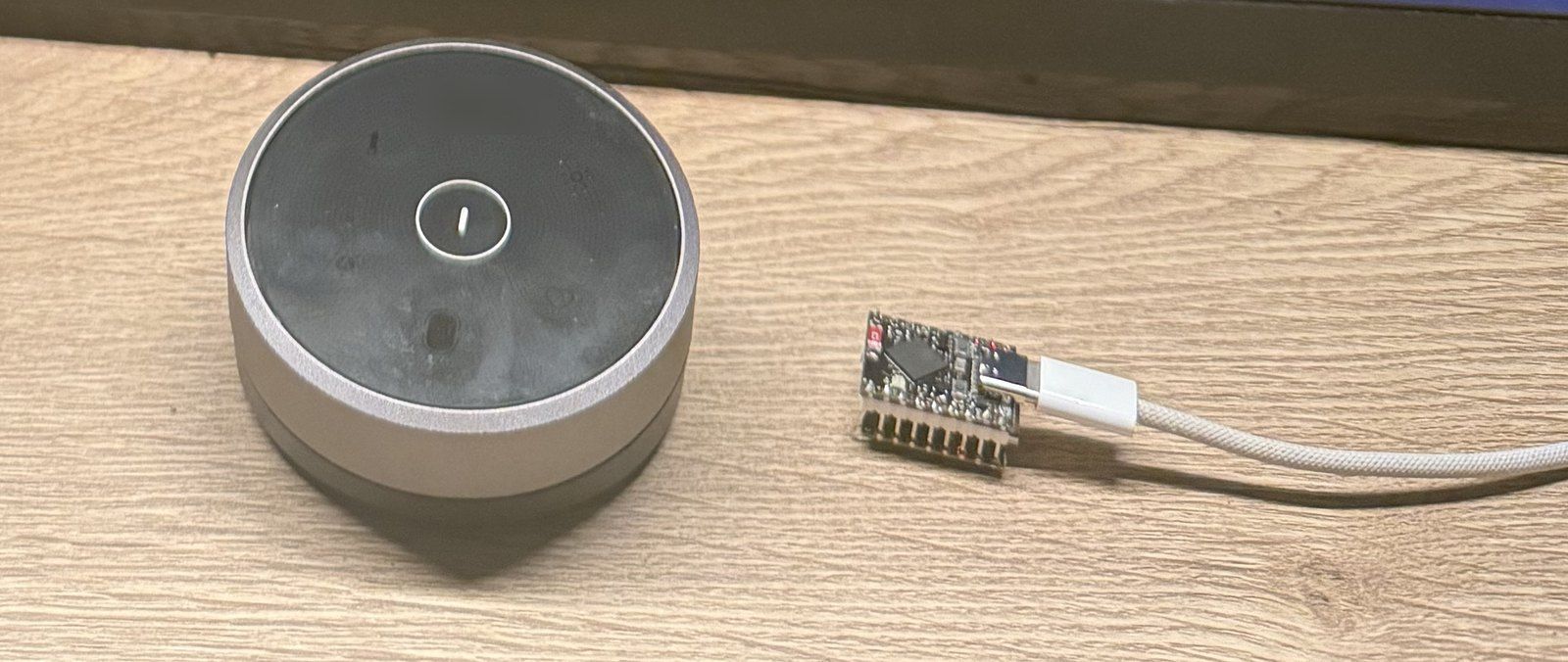
The listener became the radio half of my Home Assistant bridge. The S3 handles the radio, an ESP32-C3 runs ESPHome, and they talk over two UART wires. To keep it small I soldered the two boards into a stack, antenna over antenna, which looked like a good way to deafen the radio. So I measured before trusting it.
9Still unknown
FA/FB/FC xx every few seconds. Probably its light sensor; unproven.91 00 around the favourite recall. My early sniffer never caught it, so its meaning is still open.10Legal and safety notes
Credits
This builds on other people's work. Djoko-cli decoded the Halo's radio protocol; their notes were the map for section 2, and the open questions in them were where I started testing. Junyi-99's halo-esp32s3 made the S3 send Halo packets and check the ACK, on top of esp-sdr (raw I/Q receive on the ESP32) and esp-sdr-zephyr (capture and playback on the S3), which also document the ADC ring mode in section 5. halo-nrf52840 gave the colour temperature range. What's new here is listed at the top.
And thanks to everyone in the Home Assistant forum thread who kept poking at this lamp.
Not affiliated with or endorsed by BenQ.