
Adafruit FunHouse
ESP32-S2 board with sensors, screen, and buttons - ideal for smart home control panels and STEM projects.

Pinout
31 pins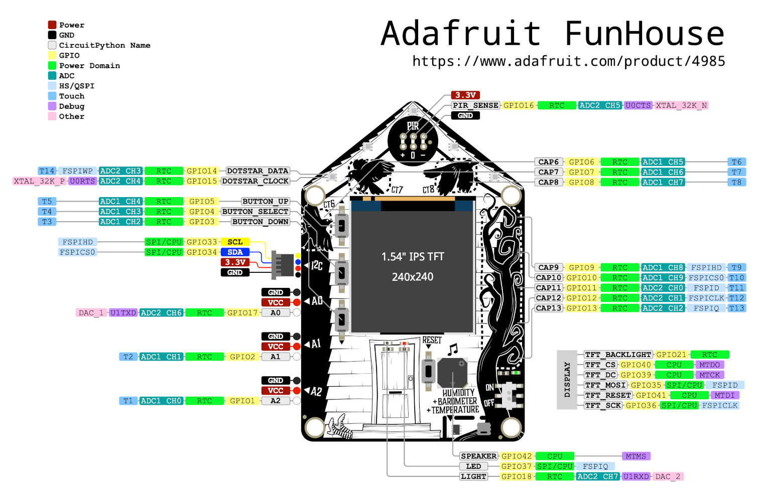
| Pin | GPIO | Labels | Status | Capabilities | Notes |
|---|---|---|---|---|---|
| 1 | 0 | PIN_BUTTON4 | strapping | - | |
| 2 | 1 | A2PWM | safe | adc | |
| 3 | 2 | A1PWM | safe | adc | |
| 4 | 3 | PIN_BUTTON1PWM | safe | - | |
| 5 | 4 | PIN_BUTTON2PWM | safe | - | |
| 6 | 5 | PIN_BUTTON3PWM | safe | - | |
| 7 | 6 | T6PWM | safe | touch | |
| 8 | 7 | T7PWM | safe | touch | |
| 9 | 8 | T8PWM | safe | touch | |
| 10 | 9 | T9PWM | strapping | touch | |
| 11 | 10 | T10PWM | strapping | touch | |
| 12 | 11 | T11PWM | strapping | touch | |
| 13 | 12 | T12PWM | strapping | touch | |
| 14 | 13 | T13PWM | strapping | touch | |
| 15 | 14 | PIN_DOTSTAR_DATAPWM | strapping | - | |
| 16 | 15 | PIN_DOTSTAR_CLOCKPWM | strapping | - | |
| 17 | 16 | SENSOR_PIRPWM | strapping | - | |
| 18 | 17 | A0DAC1PWM | safe | adc · dac | |
| 19 | 18 | SENSOR_LIGHTA3DAC2PWM | safe | adc · dac | |
| 20 | 21 | TFT_BACKLIGHTPWM | safe | - | |
| 21 | 33 | SCLPWM | strapping | i2c | |
| 22 | 34 | SDAPWM | strapping | i2c | |
| 23 | 35 | MOSIPWM | strapping | spi | |
| 24 | 36 | SCKPWM | strapping | spi | |
| 25 | 37 | LED_BUILTINMISOPWM | strapping | spi | |
| 26 | 39 | TFT_DCPWM | strapping | - | |
| 27 | 40 | TFT_CSSSPWM | strapping | spi | |
| 28 | 41 | TFT_RESETPWM | strapping | - | |
| 29 | 42 | SPEAKERPWM | strapping | - | |
| 30 | 43 | TXPWM | uart | uart | |
| 31 | 44 | RXPWM | uart | uart |
Start with these
13 pins with no boot or system involvementFreely assignable - no strapping, flash, USB or JTAG duties. Ideal first picks for buttons, sensors and LEDs.
Fine - with a little care
sampled at boot or shared with debug/serial| Pin | Label | What to know | Role |
|---|---|---|---|
| PIN_BUTTON4 | GPIO0 | Must be pulled high for normal boot; pulling low at reset enters bootloader (download mode). Also serves as SPI flash data-in (SPID) line when using external flash memory. | Strapping |
| T9 | FSPIHD | IO MUX pin of the general-purpose SPI2 (FSPI) bus, not of the in-package flash - that sits on GPIO26-32. The datasheet does not restrict it, so it is only taken if your board wires flash, an SD card or a display to FSPI. | Other |
| T10 | FSPICS0 | IO MUX pin of the general-purpose SPI2 (FSPI) bus, not of the in-package flash - that sits on GPIO26-32. The datasheet does not restrict it, so it is only taken if your board wires flash, an SD card or a display to FSPI. | Other |
| T11 | FSPID | IO MUX pin of the general-purpose SPI2 (FSPI) bus, not of the in-package flash - that sits on GPIO26-32. The datasheet does not restrict it, so it is only taken if your board wires flash, an SD card or a display to FSPI. | Other |
| T12 | FSPICLK | IO MUX pin of the general-purpose SPI2 (FSPI) bus, not of the in-package flash - that sits on GPIO26-32. The datasheet does not restrict it, so it is only taken if your board wires flash, an SD card or a display to FSPI. | Other |
| T13 | FSPIQ | IO MUX pin of the general-purpose SPI2 (FSPI) bus, not of the in-package flash - that sits on GPIO26-32. The datasheet does not restrict it, so it is only taken if your board wires flash, an SD card or a display to FSPI. | Other |
| PIN_DOTSTAR_DATA | FSPIWP | IO MUX pin of the general-purpose SPI2 (FSPI) bus, not of the in-package flash - that sits on GPIO26-32. The datasheet does not restrict it, so it is only taken if your board wires flash, an SD card or a display to FSPI. | Other |
| PIN_DOTSTAR_CLOCK | XTAL_32K_P | If an external 32 kHz crystal is used for RTC, this pin is dedicated to the crystal and cannot be used as GPIO. | Other |
| SENSOR_PIR | XTAL_32K_N | If using an external 32 kHz crystal, this pin is connected to the crystal and should not be used as general I/O. | Other |
| TFT_DC | MTCK | Used for JTAG debugging interface; using this pin for other purposes will disable JTAG clock input. | Other |
| TFT_CS | MTDO | Part of JTAG interface (TDO); should be avoided as GPIO if JTAG debugging is needed. | Other |
| TFT_RESET | MTDI | Part of JTAG interface (TDI); avoid using as GPIO to retain ability for JTAG debug. | Other |
| SPEAKER | MTMS | JTAG TMS pin; should not be repurposed if JTAG debugging or programming via JTAG is required. | Other |
Only if you know the tricks
wired to flash or USB - expect a fight| Pin | Label | What to know | Role |
|---|---|---|---|
| SCL | SPIIO4 (GPIO33) | The datasheet keeps GPIO33-37 for "the higher 4 bits data line interface and DQS interface for the SPI0/1 interface in 8-line SPI mode, and can be GPIO pins if the chip is not connected to flash or PSRAM in 8-line SPI mode". Quad-SPI parts leave it free. | Flash |
| SDA | SPIIO5 (GPIO34) | The datasheet keeps GPIO33-37 for "the higher 4 bits data line interface and DQS interface for the SPI0/1 interface in 8-line SPI mode, and can be GPIO pins if the chip is not connected to flash or PSRAM in 8-line SPI mode". Quad-SPI parts leave it free. | Flash |
| MOSI | SPIIO6 (GPIO35) | The datasheet keeps GPIO33-37 for "the higher 4 bits data line interface and DQS interface for the SPI0/1 interface in 8-line SPI mode, and can be GPIO pins if the chip is not connected to flash or PSRAM in 8-line SPI mode". Quad-SPI parts leave it free. | Flash |
| SCK | SPIIO7 (GPIO36) | The datasheet keeps GPIO33-37 for "the higher 4 bits data line interface and DQS interface for the SPI0/1 interface in 8-line SPI mode, and can be GPIO pins if the chip is not connected to flash or PSRAM in 8-line SPI mode". Quad-SPI parts leave it free. | Flash |
| LED_BUILTIN | SPIDQS (GPIO37) | The datasheet keeps GPIO33-37 for "the higher 4 bits data line interface and DQS interface for the SPI0/1 interface in 8-line SPI mode, and can be GPIO pins if the chip is not connected to flash or PSRAM in 8-line SPI mode". Quad-SPI parts leave it free. | Flash |
Pinout notes All 31 pins on the Adafruit FunHouse are usable GPIO. Peripheral wiring is straightforward: I²C is mapped to SDA on GPIO34 and SCL on GPIO33; the SPI bus…
All 31 pins on the Adafruit FunHouse are usable GPIO.
Peripheral wiring is straightforward: I²C is mapped to SDA on GPIO34 and SCL on GPIO33; the SPI bus (MOSI, MISO, SCK, SS) is broken out in full; TX/RX on GPIO43 and GPIO44 cover serial logging and flashing.
Beyond plain digital I/O you get 4 ADC-capable pins for sensors and battery monitoring, 8 capacitive-touch inputs and 2 true DAC outputs.
13 of the exposed pins carry boot-time or system duties on the ESP32-S2 (PIN_BUTTON4, T9, T10 and 10 more) - check the guidance above before wiring anything to them. A2, A1, PIN_BUTTON1, PIN_BUTTON2 and 9 more are free of any such role - the safest first picks.
Getting started
flash your first firmware in ~2 minutesBoard: ESP32S2 Dev Module USB CDC On Boot: Enabled Flash Size: 4MB (32Mb) Flash Mode: DIO PSRAM: QSPI PSRAM Partition Scheme: Default 4MB with spiffs (1.2MB APP/1.5MB SPIFFS) Upload Speed: 921600
// toggle GPIO1 - wire an LED and resistor to it
void setup() {
  pinMode(1, OUTPUT);
}
void loop() {
  digitalWrite(1, HIGH); delay(500);
  digitalWrite(1, LOW);  delay(500);
}[env:adafruit_funhouse_esp32s2]
platform = espressif32
board = esp32-s2-saola-1
framework = arduino
monitor_speed = 115200
upload_speed = 921600
board_build.arduino.memory_type = qio_qspi
build_flags = -DBOARD_HAS_PSRAMesp32-s2-saola-1 - or type it after board =.esp32:
board: esp32-s2-saola-1
variant: esp32s2
framework:
type: esp-idf
psram:
mode: quad
speed: 80MHz
# blink - GPIO1
output:
- platform: gpio
pin: 1
id: led_out
light:
- platform: binary
name: "LED"
output: led_outesp32-s2-saola-1 (same ids as PlatformIO).esptool.py --chip esp32s2 --port /dev/ttyACM0 \
--baud 921600 write_flash 0x1000 firmware.bin--port = your /dev/tty* (macOS/Linux) or COMx (Windows).Specifications
ESP32-S2 · 85 × 56 mm · vs other ESP32 chips →About this board
Inside sits the ESP32-S2 - a single-core Xtensa with native USB-OTG and no Bluetooth.
At $34.95 it's on the expensive side for an ESP32-S2 board - most land around $20.
Around the module: 2MB (QSPI) PSRAM, a TFT 1.54" 240x240 display, a STEMMA QT connector, a speaker, an addressable RGB LED (GPIO14), an environmental sensor (AHT20), an ambient-light sensor and Up/Down/Select/Boot/Reset buttons.
It flashes over native USB - no serial-converter driver needed, which isn't a given among ESP32-S2 boards.
- DPS310 barometric pressure and temperature sensor (I2C 0x77)
- Five DotStar RGB LEDs (data GPIO14, clock GPIO15)
- PIR motion sensor socket on GPIO16 (Mini PIR not included)
- Three STEMMA 3-pin JST I/O ports for NeoPixels, servos, relays or speaker
- Capacitive touch - three pads plus a five-segment slider
Where to buy
prices are typical street pricesResources
Similar boards


