
Elecrow CrowPanel Rotary 2.1 (ESP32-S3)
Round 2.1" 480x480 IPS knob display on an ESP32-S3 - rotary encoder plus capacitive touch, official ESPHome support, and the smart home knob we actually enjoy using.

Elecrow CrowPanel Rotary 2.1 (ESP32-S3) Pinout
29 pins| Pin | GPIO | Labels | Status | Capabilities | Notes |
|---|---|---|---|---|---|
| 1 | 0 | IO0BOOT | strapping | - | BOOT button - hold at power-up for download mode |
| 2 | 3 | IO3LCD_R | strapping | - | Internal - RGB panel data |
| 3 | 4 | IO4ENC_A | safe | - | Rotary encoder phase A (pull-up) - swap with IO42 if direction is inverted |
| 4 | 5 | IO5LCD_B | safe | - | Internal - RGB panel data |
| 5 | 6 | IO6LCD_BL | safe | pwm | Display backlight - LEDC PWM (19.5kHz in the official config) |
| 6 | 7 | IO7LCD_VSYNC | safe | - | Internal - RGB panel vertical sync |
| 7 | 8 | IO8LCD_R | safe | - | Internal - RGB panel data |
| 8 | 9 | IO9LCD_G | strapping | - | Internal - RGB panel data |
| 9 | 10 | IO10LCD_G | strapping | - | Internal - RGB panel data |
| 10 | 11 | IO11LCD_G | strapping | - | Internal - RGB panel data |
| 11 | 12 | IO12LCD_G | strapping | - | Internal - RGB panel data |
| 12 | 13 | IO13LCD_G | strapping | - | Internal - RGB panel data |
| 13 | 14 | IO14LCD_G | strapping | - | Internal - RGB panel data |
| 14 | 15 | IO15LCD_HSYNC | safe | - | Internal - RGB panel horizontal sync |
| 15 | 16 | IO16LCD_CS | safe | spi | Internal - ST7701S 3-wire SPI init chip select |
| 16 | 17 | IO17LCD_R | safe | - | Internal - RGB panel data |
| 17 | 18 | IO18LCD_R | safe | - | Internal - RGB panel data |
| 18 | 21 | IO21LCD_B | safe | - | Internal - RGB panel data |
| 19 | 38 | IO38SDA | safe | i2c | I2C bus - CST816 touch (0x15) and PCF8574 expander (0x21); also on the I2C expansion connector |
| 20 | 39 | IO39SCL | strapping | i2c | I2C bus - same shared bus as IO38 |
| 21 | 40 | IO40LCD_DE | strapping | - | Internal - RGB panel data enable |
| 22 | 41 | IO41LCD_PCLK | strapping | - | Internal - RGB panel pixel clock (18MHz) |
| 23 | 42 | IO42ENC_B | strapping | - | Rotary encoder phase B (pull-up) |
| 24 | 43 | IO43TXD0 | uart | uart | UART0 - USB-C flashing/logs and the UART expansion connector |
| 25 | 44 | IO44RXD0 | uart | uart | UART0 - USB-C flashing/logs and the UART expansion connector |
| 26 | 45 | IO45LCD_B | strapping | - | Internal - RGB panel data |
| 27 | 46 | IO46LCD_R | strapping | - | Internal - RGB panel data |
| 28 | 47 | IO47LCD_B | strapping | - | Internal - RGB panel data |
| 29 | 48 | IO48LCD_B | strapping | - | Internal - RGB panel data |
Start with these
11 pins with no boot or system involvementFreely assignable - no strapping, flash, USB or JTAG duties. Ideal first picks for buttons, sensors and LEDs.
Fine - with a little care
18 pins · 12 things to knowIO0 Bootstrapping pin (Chip boot mode selection) Strapping
Must be pulled high (default) or low (to enter UART download mode) at reset. Using it for other functions can interfere with boot mode configuration.
IO3 Bootstrapping pin (controls JTAG signal source) Strapping
Sampled at reset to select JTAG interface (USB Serial/JTAG controller vs. external pins). Improper use can disable external JTAG or alter debug interface.
IO9IO10IO11IO12IO13IO14 General-purpose SPI2 (FSPI) IO MUX pins Other
IO MUX pin of the general-purpose SPI2 (FSPI) bus, not of the in-package flash - that sits on GPIO26-32. The datasheet lists it as a priority-2 pin ("can be freely used without restrictions"), so it is only taken if your board wires flash, an SD card or a display to FSPI.
- IO9General-purpose SPI2 (FSPI) IO MUX pin - hold/data line (FSPIHD)
- IO10General-purpose SPI2 (FSPI) IO MUX pin - chip select (FSPICS0)
- IO11General-purpose SPI2 (FSPI) IO MUX pin - data in (FSPID)
- IO12General-purpose SPI2 (FSPI) IO MUX pin - clock (FSPICLK)
- IO13General-purpose SPI2 (FSPI) IO MUX pin - data out (FSPIQ)
- IO14General-purpose SPI2 (FSPI) IO MUX pin - write-protect/data line (FSPIWP)
IO39 JTAG test clock (MTCK); IO MUX alternates CLK_OUT3 and SUBSPICS1 (chip select on the alternative SUBSPI memory bus, unused on standard modules) JTAG
Default JTAG TCK - keep it free if you debug over JTAG. It is not a flash or PSRAM line on standard modules: those sit on GPIO26-37.
IO40 JTAG test data out pin (MTDO) JTAG
Default JTAG TDO output for debugging. Using it as GPIO will interfere with JTAG debugging functionality.
IO41 JTAG test data in pin (MTDI) JTAG
Default JTAG TDI input for debugging. Should be reserved for JTAG or left unused if JTAG is to remain available.
IO42 JTAG test mode select pin (MTMS) JTAG
Default JTAG TMS signal for debugging. Using this pin for other purposes will disable the JTAG interface (unless JTAG is rerouted to USB).
IO43 UART0 transmit pin (U0TXD), default serial console TX UART
Used for bootloader output and UART console logs. If repurposed, you will lose the default serial output (and programming via UART0).
IO44 UART0 receive pin (U0RXD), default serial console RX UART
Used for bootloader input (download mode via serial). If repurposed, you cannot use the default UART0 download mode for programming the chip.
IO45 Bootstrapping pin (selects VDD_SPI flash voltage) Strapping
Determines flash/PSRAM power voltage (3.3 V vs 1.8 V) at boot. Must match hardware configuration; using as GPIO can upset flash supply setting.
IO46 Bootstrapping pin (used with GPIO0 for boot mode; controls ROM log output) Strapping
Must be at a defined level during reset (with GPIO0) to select normal or download boot and UART/USB print mode. This pin is input-only (no output drive), so it should be left for its intended strapping function.
IO47IO48 Octal SPI differential clock legs (SPICLK_P/N_DIFF), used only by the 1.8 V octal flash/PSRAM variants Other
Only the 1.8 V octal parts (ESP32-S3R8V, ESP32-S3R16V) run the differential memory clock here, and on those the pin works at 1.8 V instead of 3.3 V. On the common 3.3 V modules it is a normal GPIO - several devkits drive their RGB LED from GPIO48.
- IO47Octal SPI differential clock positive leg (SPICLK_P_DIFF), used only by the 1.8 V octal flash/PSRAM variants
- IO48Octal SPI differential clock negative leg (SPICLK_N_DIFF), used only by the 1.8 V octal flash/PSRAM variants
The Elecrow CrowPanel Rotary 2.1 (ESP32-S3) pinout brings out 29 GPIO pins - every one of them usable in your project.
For peripherals, I²C is mapped to SDA on GPIO38 and SCL on GPIO39.
On the analog side there are PWM on 1 pins.
If you want zero surprises, IO4, IO5, IO6, IO7 and 7 more are free of any such role - the safest first picks. 18 of the exposed pins carry boot-time or system duties on the ESP32-S3 (IO0, IO3, IO9 and 15 more).
Pinout notes Most pins drive the 480x480 panel: an RGB bus with red on IO46/IO3/IO8/IO18/IO17, green on IO14/IO13/IO12/IO11/IO10/IO9, blue on IO5/IO45/IO48/IO47/IO21, plus…
Most pins drive the 480x480 panel: an RGB bus with red on IO46/IO3/IO8/IO18/IO17, green on IO14/IO13/IO12/IO11/IO10/IO9, blue on IO5/IO45/IO48/IO47/IO21, plus CS on IO16 (3-wire SPI init), DE on IO40, HSYNC/VSYNC on IO15/IO7 and PCLK on IO41 at 18MHz. The backlight is LEDC PWM on IO6.
The rotary encoder is on IO4 (A) and IO42 (B) with pull-ups - swap them if your knob direction is inverted. I2C runs on IO38 (SDA) / IO39 (SCL) and hosts the CST816 touch controller (0x15) and a PCF8574 expander at 0x21 that owns the housekeeping lines: touch reset (P0), touch interrupt (P2), LCD power (P3), LCD reset (P4) and - importantly - the encoder push button on P5.
Expansion is through the UART and I2C connectors and a 12-pin FPC rather than a pin header. Firmware must walk the PCF8574 power-on sequence (LCD power, then resets) before the panel or touch respond - Elecrow's ESPHome example and our review config both handle it on boot.
Getting started
flash your first firmware in ~2 minutesBoard: ESP32S3 Dev Module Flash Size: 16MB (128Mb) PSRAM: QSPI PSRAM Partition Scheme: 16M Flash (3MB APP/9.9MB FATFS) Upload Speed: 921600
// toggle GPIO4 - wire an LED and resistor to it
void setup() {
  pinMode(4, OUTPUT);
}
void loop() {
  digitalWrite(4, HIGH); delay(500);
  digitalWrite(4, LOW);  delay(500);
}[env:elecrow-crowpanel-rotary-2-1]
platform = espressif32
board = esp32-s3-devkitc-1
framework = arduino
monitor_speed = 115200
upload_speed = 921600
board_build.arduino.memory_type = qio_qspi
build_flags = -DBOARD_HAS_PSRAMesp32-s3-devkitc-1 - or type it after board =.esp32:
board: esp32-s3-devkitc-1
variant: esp32s3
framework:
type: esp-idf
psram:
mode: quad
speed: 80MHz
# blink - GPIO4
output:
- platform: gpio
pin: 4
id: led_out
light:
- platform: binary
name: "LED"
output: led_outesp32-s3-devkitc-1 (same ids as PlatformIO).esptool.py --chip esp32s3 --port /dev/ttyACM0 \
--baud 921600 write_flash 0x0 firmware.bin--port = your /dev/tty* (macOS/Linux) or COMx (Windows).Good to know
board-specific quirks worth 60 seconds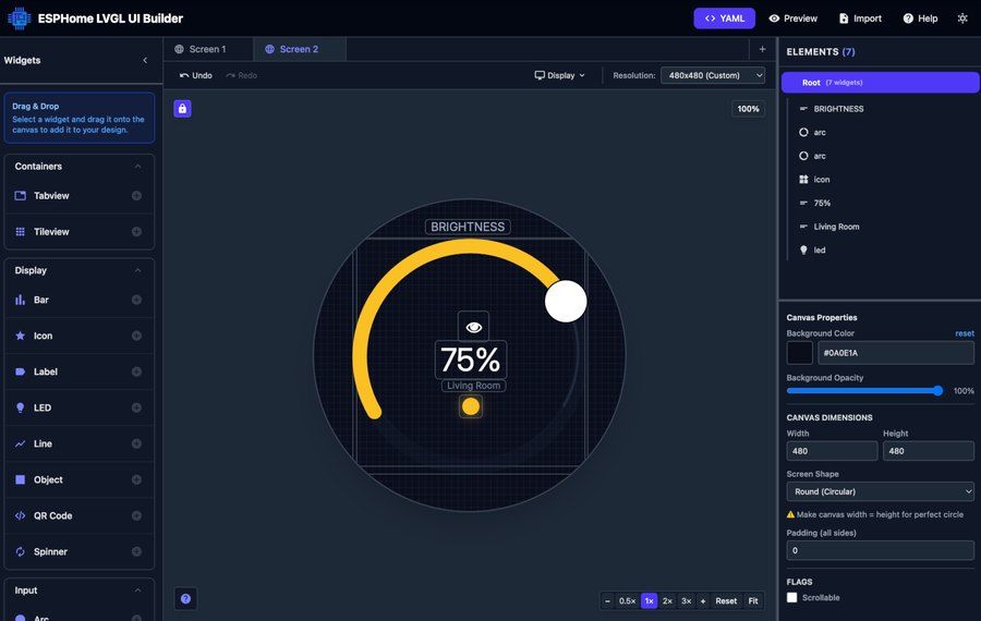
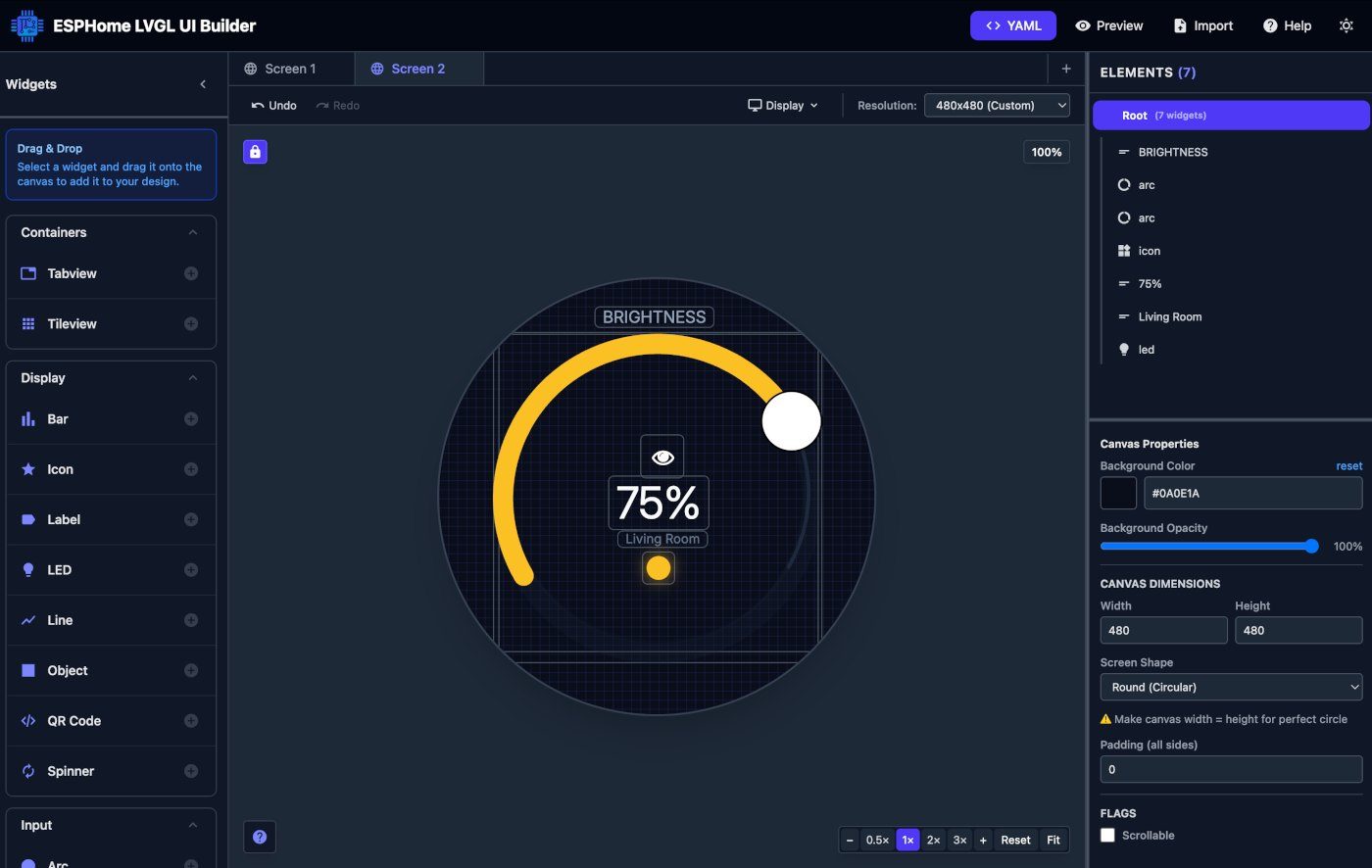
Round RGB displays used to mean raw C, custom drivers and init-sequence archaeology. Since January 2026 Elecrow ships official ESPHome examples for this panel - and we designed our review UI visually in the ESPHome LVGL Designer instead of hand-coding coordinates.
Copy the ST7701S init_sequence from Elecrow's official YAML verbatim - one wrong byte gives you garbage or a black screen.
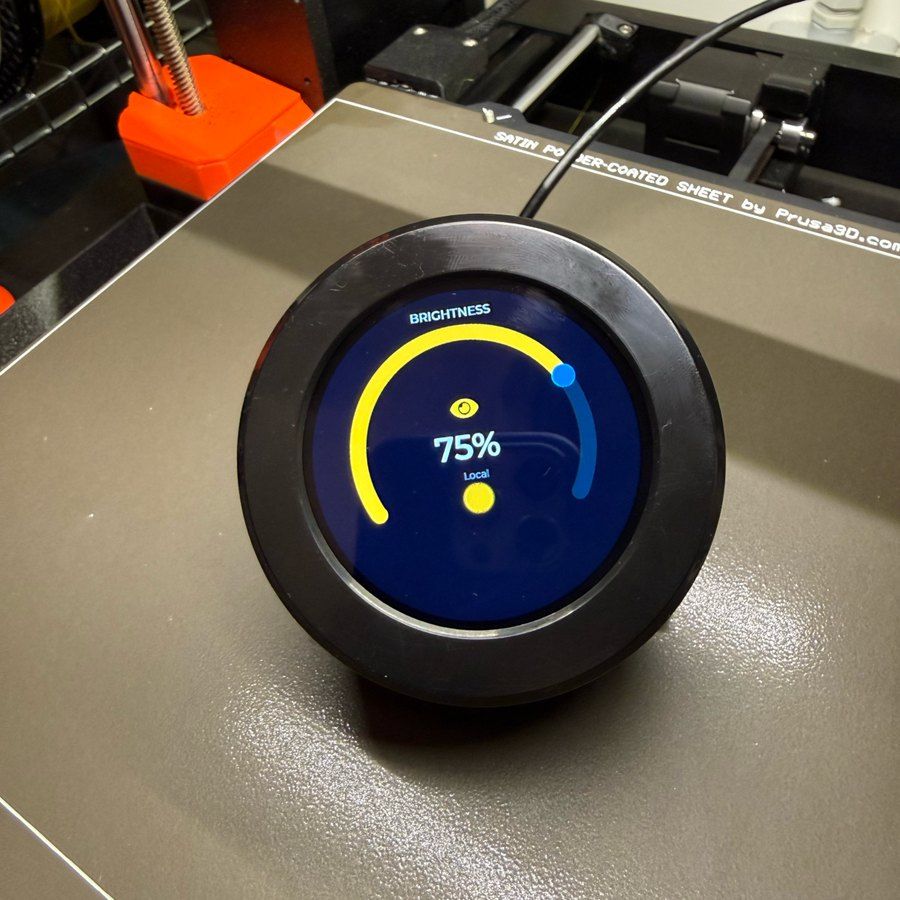
A PCF8574 expander at I2C 0x21 owns the housekeeping: LCD power and reset, touch reset and interrupt, and the encoder's push button (P5). Rotation is on real GPIOs (IO4/IO42), but the click comes over I2C - firmware expecting a button GPIO will wait forever.
If the knob direction feels inverted, swap pin A and B (IO4/IO42) in your config - it's the most common mix-up on this board.
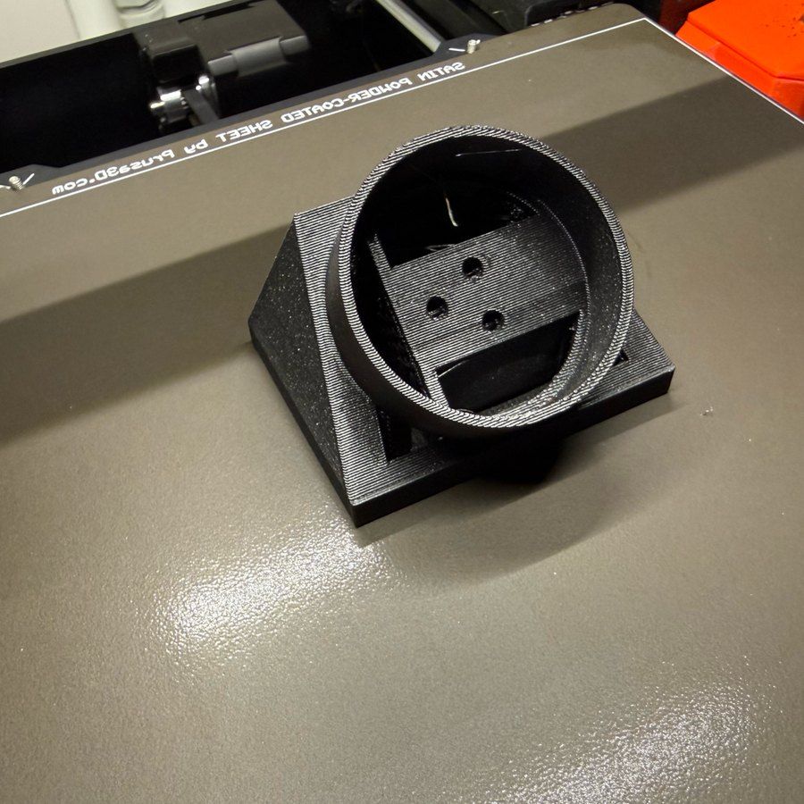
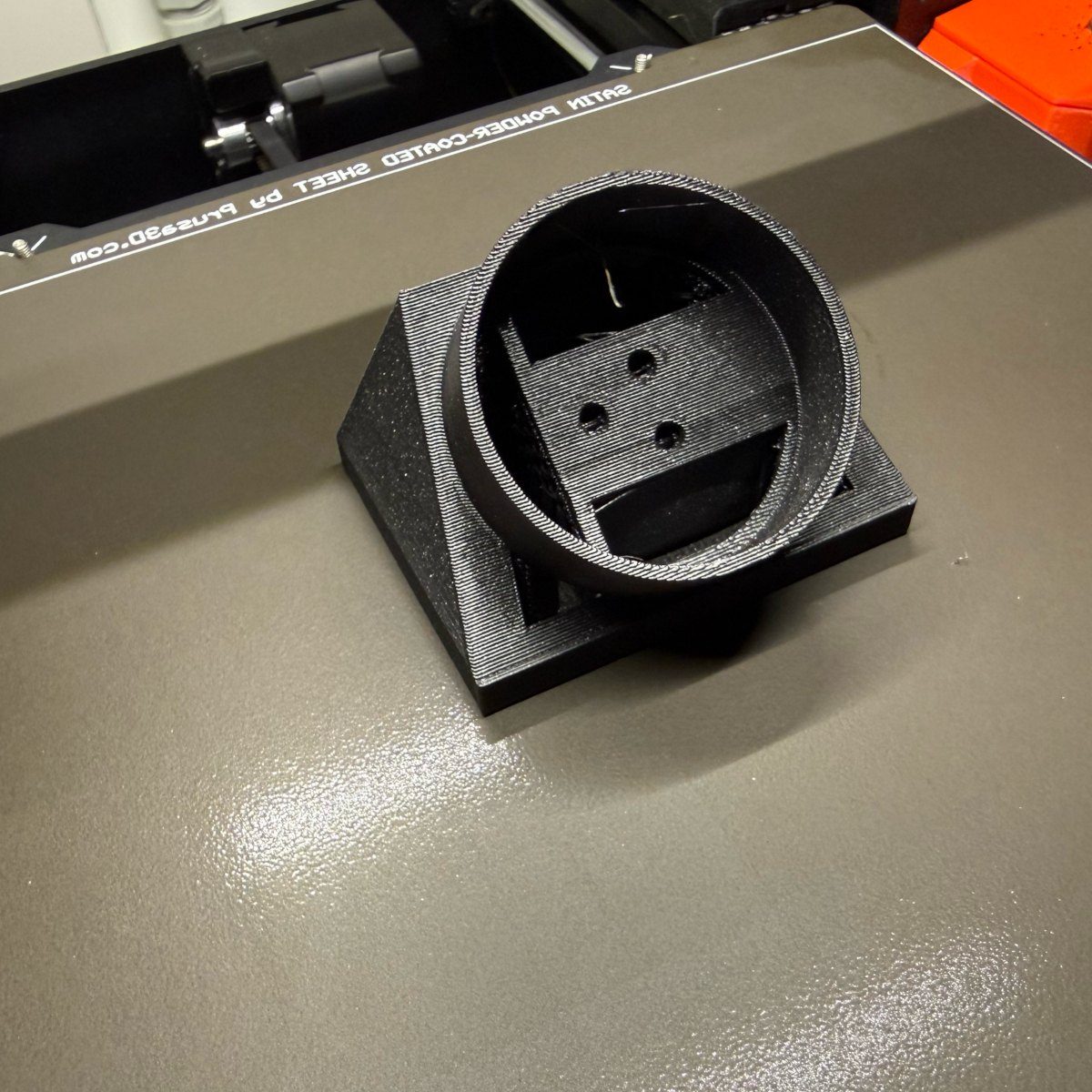
The screen and knob feel premium; the stock aluminum-and-plastic shell doesn't quite match them. We 3D-printed a replacement case (files linked in the review) and the whole device jumped a quality tier - it's an easy weekend upgrade if you have a printer. For a smaller or cheaper build, Elecrow's 1.28" 240x240 rotary sibling uses the same interaction model - but the 2.1" panel is the one worth the extra few…
The screen and knob feel premium; the stock aluminum-and-plastic shell doesn't quite match them. We 3D-printed a replacement case (files linked in the review) and the whole device jumped a quality tier - it's an easy weekend upgrade if you have a printer.
For a smaller or cheaper build, Elecrow's 1.28" 240x240 rotary sibling uses the same interaction model - but the 2.1" panel is the one worth the extra few dollars.
Gallery
5 photos
Specifications
ESP32-S3 · 79 × 79 mm · vs other ESP32 chips →Dimensions
About this board
At its core is the ESP32-S3 - a dual-core Xtensa with vector extensions suited to AI workloads.
Expect to pay about $35.70 - above the ~$29 typical for ESP32-S3 boards.
29 GPIO are broken out - more than most ESP32-S3 boards, so the pin budget is rarely the constraint.
Onboard you'll find 8MB PSRAM, an IPS LCD (round) 2.1" 480x480 display with touch, a rotary encoder, status LEDs (Power, ambient ring) and Boot/Reset/encoder press buttons.
The Elecrow CrowPanel Rotary 2.1 is a round 480x480 IPS display with a physical rotary knob wrapped around it, built on an ESP32-S3R8 (16 MB flash, 8 MB PSRAM). We reviewed it in early 2026 and it became the rare review unit that stayed on the desk afterwards - a rotary display is an interaction device that happens to have a screen, and that makes it genuinely different from another rectangle.
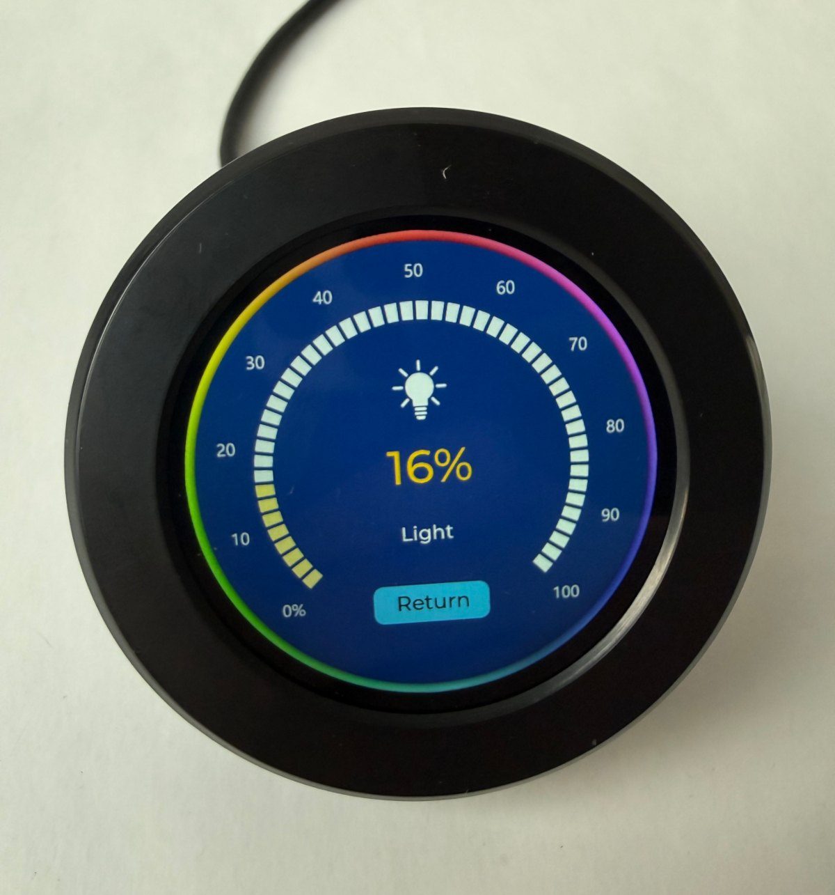
The screen is the standout: 480x480 on 2.1 inches is dense enough that pixels disappear, and it's a proper IPS panel driven by an ST7701S over an RGB parallel bus. Input is triple-redundant in the best way - twist the knob (CW/CCW), press it to confirm, or just touch the screen (CST816 capacitive controller). Brightness, volume, temperature, timers: anything that's fundamentally "one value" feels better on this than on any touchscreen slider.
The software story matured recently: Elecrow ships official ESPHome examples since January 2026, including the fiddly ST7701S init sequence that historically made round RGB displays painful. Our review builds a two-way brightness controller on it - physical knob plus LVGL touch arc - designed in our own ESPHome LVGL Designer.
Honest cons from our time with it: the stock aluminum-plus-plastic shell looks better in renders than in hand (we ended up 3D-printing a case, files linked in the review), and several control signals route through a PCF8574 I/O expander rather than real GPIOs, which you must understand before writing your own firmware. Neither changed the verdict - as a smart home knob it's the most fun ESP32 display we've tested.
- Round 2.1" 480x480 IPS panel (ST7701S, RGB parallel bus) - high enough density that pixels disappear
- Physical rotary knob (CW/CCW + press) around the screen, plus CST816 capacitive touch
- ESP32-S3R8 - 16 MB flash, 8 MB PSRAM
- Official ESPHome example configs from Elecrow (since January 2026), full init sequence included
- PCF8574 I/O expander (I2C 0x21) manages LCD power/reset, touch reset/interrupt and the encoder button
- Backlight on LEDC PWM (IO6) - smooth dimming at 19.5kHz, no whine
- UART and I2C expansion connectors plus a 12-pin FPC
- Ambient LED ring and power LED; Boot and Reset buttons
- 79 x 79 x 30 mm, 80 g; a 1.28" 240x240 sibling exists for smaller builds
FAQ
5 common questionsDoes the CrowPanel Rotary 2.1 work with ESPHome?›
Why doesn't my display or touch respond with custom firmware?›
Where is the encoder's push button?›
Is the knob any good compared to cheaper round displays?›
What would we actually use it for?›
Where to buy
prices are typical street pricesResources
Similar boards

