
Elecrow ThinkNode M2 (ESP32-S3)
Pocket Meshtastic node on an ESP32-S3 - SX1262 LoRa, 1.3" OLED, 1000mAh battery and an integrated antenna, preloaded and working minutes out of the box. Reviewed head-to-head against its nRF52840 sibling.

Elecrow ThinkNode M2 (ESP32-S3) Pinout
21 pins| Pin | GPIO | Labels | Status | Capabilities | Notes |
|---|---|---|---|---|---|
| 1 | 0 | IO0BOOT | strapping | - | BOOT button - hold at power-up for download mode |
| 2 | 3 | IO3LORA_DIO1 | strapping | - | Internal - SX1262 DIO1 interrupt |
| 3 | 4 | IO4PWR_BTN | safe | - | Power button (active high) |
| 4 | 5 | IO5BUZZER | safe | pwm | Internal - buzzer |
| 5 | 6 | IO6PWR_LED | safe | - | Internal - power LED |
| 6 | 7 | IO7USB_DETECT | safe | - | Internal - external/USB power detection |
| 7 | 10 | IO10LORA_CS | strapping | spi | Internal - SX1262 chip select |
| 8 | 11 | IO11LORA_MOSI | strapping | spi | Internal - SX1262 SPI MOSI |
| 9 | 12 | IO12LORA_SCK | strapping | spi | Internal - SX1262 SPI clock |
| 10 | 13 | IO13LORA_MISO | strapping | spi | Internal - SX1262 SPI MISO |
| 11 | 14 | IO14LORA_BUSY | strapping | - | Internal - SX1262 busy signal |
| 12 | 15 | IO15SCL | safe | i2c | Internal I2C - SH1106 OLED |
| 13 | 16 | IO16SDA | safe | i2c | Internal I2C - SH1106 OLED |
| 14 | 17 | IO17VBAT_ADC | safe | adc | Internal - battery voltage sense (1.548x divider, ADC2) |
| 15 | 21 | IO21LORA_RST | safe | - | Internal - SX1262 reset |
| 16 | 42 | IO42ADC_V | strapping | adc | Internal - auxiliary voltage sense |
| 17 | 43 | IO43TXD0 | uart | uart | UART0 - USB-C serial logs/flashing |
| 18 | 44 | IO44RXD0 | uart | uart | UART0 - USB-C serial logs/flashing |
| 19 | 46 | IO46OLED_PWR | strapping | - | Internal - OLED power-rail enable, drive high before display init |
| 20 | 47 | IO47FUNC_BTN | strapping | - | Function button |
| 21 | 48 | IO48LORA_PWR | strapping | - | Internal - SX1262 power-rail enable, drive high before radio init |
Start with these
8 pins with no boot or system involvementFreely assignable - no strapping, flash, USB or JTAG duties. Ideal first picks for buttons, sensors and LEDs.
Fine - with a little care
13 pins · 8 things to knowIO0 Bootstrapping pin (Chip boot mode selection) Strapping
Must be pulled high (default) or low (to enter UART download mode) at reset. Using it for other functions can interfere with boot mode configuration.
IO3 Bootstrapping pin (controls JTAG signal source) Strapping
Sampled at reset to select JTAG interface (USB Serial/JTAG controller vs. external pins). Improper use can disable external JTAG or alter debug interface.
IO10IO11IO12IO13IO14 General-purpose SPI2 (FSPI) IO MUX pins Other
IO MUX pin of the general-purpose SPI2 (FSPI) bus, not of the in-package flash - that sits on GPIO26-32. The datasheet lists it as a priority-2 pin ("can be freely used without restrictions"), so it is only taken if your board wires flash, an SD card or a display to FSPI.
- IO10General-purpose SPI2 (FSPI) IO MUX pin - chip select (FSPICS0)
- IO11General-purpose SPI2 (FSPI) IO MUX pin - data in (FSPID)
- IO12General-purpose SPI2 (FSPI) IO MUX pin - clock (FSPICLK)
- IO13General-purpose SPI2 (FSPI) IO MUX pin - data out (FSPIQ)
- IO14General-purpose SPI2 (FSPI) IO MUX pin - write-protect/data line (FSPIWP)
IO42 JTAG test mode select pin (MTMS) JTAG
Default JTAG TMS signal for debugging. Using this pin for other purposes will disable the JTAG interface (unless JTAG is rerouted to USB).
IO43 UART0 transmit pin (U0TXD), default serial console TX UART
Used for bootloader output and UART console logs. If repurposed, you will lose the default serial output (and programming via UART0).
IO44 UART0 receive pin (U0RXD), default serial console RX UART
Used for bootloader input (download mode via serial). If repurposed, you cannot use the default UART0 download mode for programming the chip.
IO46 Bootstrapping pin (used with GPIO0 for boot mode; controls ROM log output) Strapping
Must be at a defined level during reset (with GPIO0) to select normal or download boot and UART/USB print mode. This pin is input-only (no output drive), so it should be left for its intended strapping function.
IO47IO48 Octal SPI differential clock legs (SPICLK_P/N_DIFF), used only by the 1.8 V octal flash/PSRAM variants Other
Only the 1.8 V octal parts (ESP32-S3R8V, ESP32-S3R16V) run the differential memory clock here, and on those the pin works at 1.8 V instead of 3.3 V. On the common 3.3 V modules it is a normal GPIO - several devkits drive their RGB LED from GPIO48.
- IO47Octal SPI differential clock positive leg (SPICLK_P_DIFF), used only by the 1.8 V octal flash/PSRAM variants
- IO48Octal SPI differential clock negative leg (SPICLK_N_DIFF), used only by the 1.8 V octal flash/PSRAM variants
The Elecrow ThinkNode M2 (ESP32-S3) pinout brings out 21 GPIO pins - every one of them usable in your project.
For peripherals, I²C is mapped to SDA on GPIO16 and SCL on GPIO15.
On the analog side there are 2 ADC-capable pins for sensors and battery monitoring and PWM on 1 pins.
If you want zero surprises, IO4, IO5, IO6, IO7 and 4 more are free of any such role - the safest first picks. 13 of the exposed pins carry boot-time or system duties on the ESP32-S3 (IO0, IO3, IO10 and 10 more).
Pinout notes No GPIO is broken out - the ThinkNode M2 is a finished device, and this map documents the internal wiring for firmware authors. The SX1262 LoRa radio sits on…
No GPIO is broken out - the ThinkNode M2 is a finished device, and this map documents the internal wiring for firmware authors. The SX1262 LoRa radio sits on SPI: IO12 (SCK), IO11 (MOSI), IO13 (MISO), IO10 (CS), with IO21 (reset), IO14 (busy), IO3 (DIO1) and IO48 switching the radio's power rail.
The SH1106 OLED lives on I2C (IO16 SDA / IO15 SCL) behind a switched rail on IO46 that must be enabled before the display responds. The Function button is IO47, the Power button IO4, the buzzer IO5, and the power LED IO6.
Power management: battery voltage is sensed on IO17 (ADC2, 1.548x divider), USB presence on IO7, and UART0 logs run on the usual IO43/IO44 through USB-C. All of this matches the upstream Meshtastic variant definition, which is the reference if you write custom firmware.
Getting started
flash your first firmware in ~2 minutesBoard: ESP32S3 Dev Module Flash Size: 4MB (32Mb) PSRAM: QSPI PSRAM Partition Scheme: Default 4MB with spiffs (1.2MB APP/1.5MB SPIFFS) Upload Speed: 921600
// toggle GPIO4 - wire an LED and resistor to it
void setup() {
  pinMode(4, OUTPUT);
}
void loop() {
  digitalWrite(4, HIGH); delay(500);
  digitalWrite(4, LOW);  delay(500);
}[env:elecrow-thinknode-m2]
platform = espressif32
board = esp32-s3-devkitc-1
framework = arduino
monitor_speed = 115200
upload_speed = 921600
board_build.arduino.memory_type = qio_qspi
build_flags = -DBOARD_HAS_PSRAMesp32-s3-devkitc-1 - or type it after board =.esp32:
board: esp32-s3-devkitc-1
variant: esp32s3
framework:
type: esp-idf
psram:
mode: quad
speed: 80MHz
# blink - GPIO4
output:
- platform: gpio
pin: 4
id: led_out
light:
- platform: binary
name: "LED"
output: led_outesp32-s3-devkitc-1 (same ids as PlatformIO).esptool.py --chip esp32s3 --port /dev/ttyACM0 \
--baud 921600 write_flash 0x0 firmware.bin--port = your /dev/tty* (macOS/Linux) or COMx (Windows).Good to know
board-specific quirks worth 60 seconds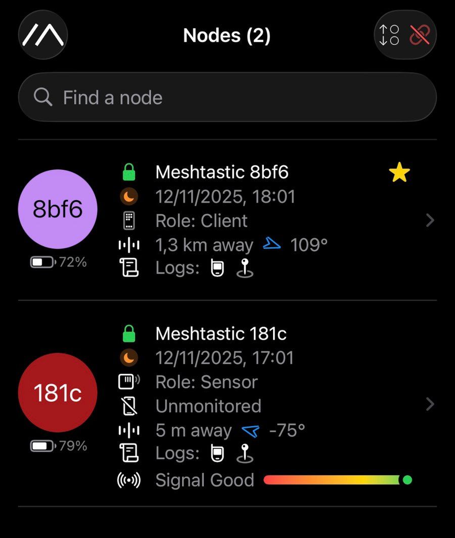
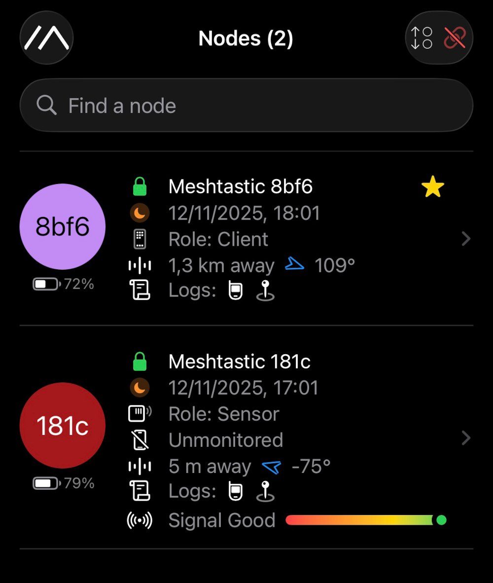
Preinstalled Meshtastic means the usual flash-and-troubleshoot evening becomes: power on, pair via Bluetooth, message. Our two review units found each other immediately, and suburban range reached several kilometers line-of-sight.
Buy the frequency variant for your region (EU 868 / US 915 MHz) - the SX1262 band is fixed by hardware filtering, not firmware.
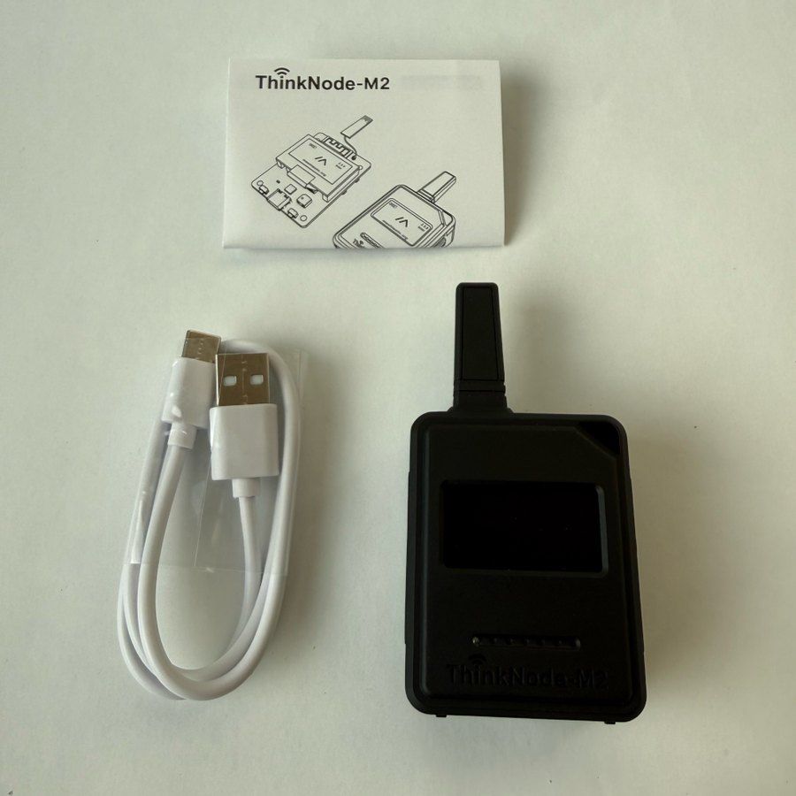
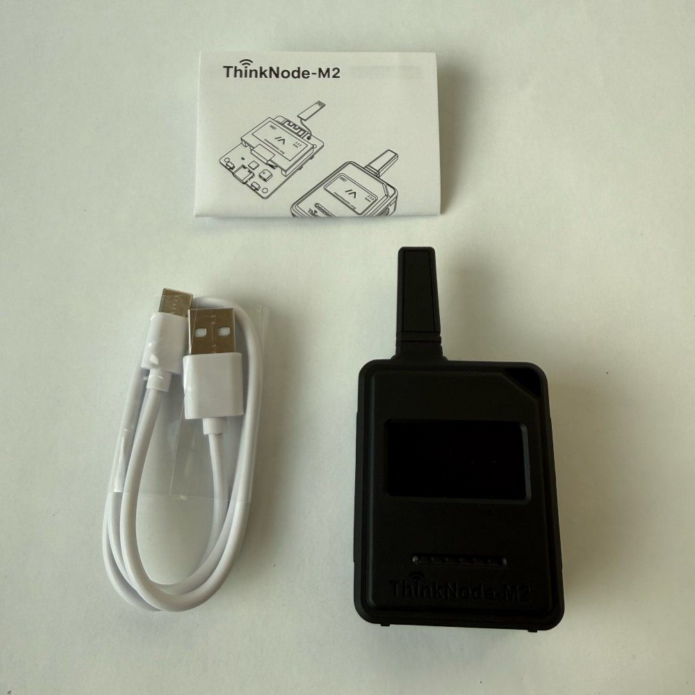
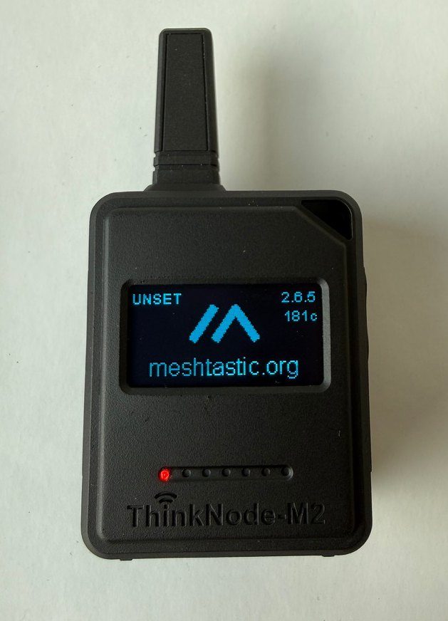
Unlike the M1 (and most LoRa handhelds), there's no antenna to screw on - it's integrated into the frame via an internal IPEX connector. The result is a genuinely pocketable 50 g unit with nothing to snap off in a backpack.
The flip side: no external antenna port for range upgrades. If you're building a rooftop or repeater node, choose hardware with an SMA connector instead.
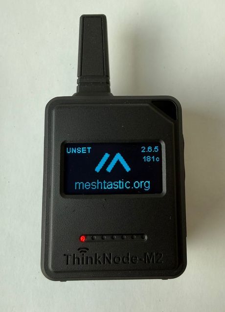
The M2's variant definition lives upstream in the Meshtastic firmware repository, which means the full internal pin map - SX1262 SPI, SH1106 I2C, buzzer, battery ADC, the OLED's power-enable on IO46 - is public. Reflash it with Arduino or ESP-IDF and it's a battery-powered LoRa dev board with a screen and case included. Writing custom firmware? Drive IO46 high before initializing the OLED and IO48 high before…
The M2's variant definition lives upstream in the Meshtastic firmware repository, which means the full internal pin map - SX1262 SPI, SH1106 I2C, buzzer, battery ADC, the OLED's power-enable on IO46 - is public. Reflash it with Arduino or ESP-IDF and it's a battery-powered LoRa dev board with a screen and case included.
Writing custom firmware? Drive IO46 high before initializing the OLED and IO48 high before the radio - both sit behind switched power rails.
Gallery
4 photos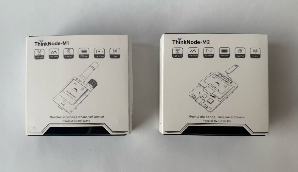
Specifications
ESP32-S3 · 88.4 × 46 mm · vs other ESP32 chips →Dimensions
About this board
At its core is the ESP32-S3 - a dual-core Xtensa with vector extensions suited to AI workloads.
Expect to pay about $21.90 - less than the ~$29 most ESP32-S3 boards go for.
Onboard you'll find 8MB PSRAM, an OLED 1.3" 128x64 display, LoRa (SX1262), a buzzer, status LEDs (Power, Charge) and Power/Function/Boot/Reset buttons.
The Elecrow ThinkNode M2 is a ready-made Meshtastic node: an ESP32-S3 (4 MB flash, 8 MB PSRAM) paired with an SX1262 LoRa radio (868/915 MHz), a 1.3-inch SH1106 OLED, a 1000mAh battery and a cased, pocketable form factor. We reviewed it head-to-head against its nRF52840 sibling, the ThinkNode M1 - and the M2 is the one we'd point ESP32 people at.
The out-of-box experience is the selling point: Meshtastic firmware comes preinstalled, so it's power on, pair the phone app over Bluetooth, and start messaging over LoRa - we had both review units talking to each other within minutes, no flashing involved. Range in our suburban testing reached several kilometers with line of sight, and 1-2 km among buildings.
Design trade-offs versus the M1: the M2 has no GPS (the M1 does), and its OLED draws power whenever it's on, where the M1's e-paper sips it - so the M1 wins on battery life and location features. The M2 counters with a snappier display, a smaller integrated antenna (nothing to screw on), a lower price, and - the reason it's on this site - the ESP32-S3 underneath, which makes it far more hackable than the Nordic-based M1.
That hackability is real: the Meshtastic firmware variant for this board is upstream, the internal wiring is documented (SX1262 on SPI, OLED on I2C, buzzer, battery ADC), and nothing stops you reflashing it with Arduino, ESP-IDF or your own LoRa firmware. As a first mesh node or a tinkerable LoRa dev unit with a screen, battery and case already solved, it's easy money at around $22.
- Meshtastic firmware preinstalled - pair the phone app and message over LoRa within minutes
- SX1262 LoRa transceiver (EU 868 / US 915 MHz) with DIO2 RF switching and TCXO
- 1.3" SH1106 OLED (128x64) behind a firmware-switched power rail
- ESP32-S3 with 4 MB flash and 8 MB PSRAM - Wi-Fi and BLE 5 alongside LoRa
- 1000mAh battery with USB-C charging, battery-voltage ADC and USB-detect sensing
- Integrated antenna in the frame (IPEX connector inside) - nothing to screw on
- Power, Function, Boot and Reset buttons plus a buzzer for alerts
- Upstream Meshtastic variant support - the internal pin map is documented and reflashing is unrestricted
- 88.4 x 46 x 23 mm cased, 50 g - genuinely pocketable
FAQ
5 common questionsDo I need to flash anything to use the ThinkNode M2?›
ThinkNode M1 or M2 - which should I buy?›
What range does it actually get?›
Can I reflash it with my own firmware?›
Does it have GPS?›
Where to buy
prices are typical street pricesResources
Similar boards

