
Espressif ESP32-S3-DevKitM-1
Compact ESP32-S3 board with rich peripheral support - ideal for secure, low-power wireless development.

Espressif ESP32-S3-DevKitM-1 Pinout
44 pins · 2.54 mm pitch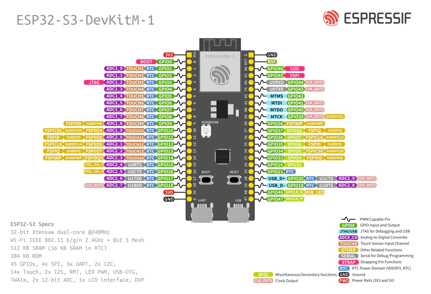
| Pin | GPIO | Labels | Status | Capabilities | Notes |
|---|---|---|---|---|---|
| 1 | - | 3V33.3V | power | - | 3.3V regulated output |
| 2 | 0 | IO0 | strapping | pwm | BOOT button |
| 3 | 1 | IO1A1T1 | safe | adc · touch · pwm | ADC1_CH0; RTC |
| 4 | 2 | IO2A2T2 | safe | adc · touch · pwm | ADC1_CH1; RTC |
| 5 | 3 | IO3A3T3 | strapping | adc · touch · pwm | ADC1_CH2; RTC |
| 6 | 4 | IO4A4T4 | safe | adc · touch · pwm | ADC1_CH3; RTC |
| 7 | 5 | IO5A5T5 | safe | adc · touch · pwm | ADC1_CH4; RTC |
| 8 | 6 | IO6A6T6 | safe | adc · touch · pwm | ADC1_CH5; RTC |
| 9 | 7 | IO7A7T7 | safe | adc · touch · pwm | ADC1_CH6; RTC |
| 10 | 8 | IO8A8T8 | safe | adc · touch · pwm | ADC1_CH7; RTC |
| 11 | 9 | IO9A9T9 | strapping | adc · touch · spi · pwm | ADC1_CH8; RTC; FSPIHD |
| 12 | 10 | IO10A10T10SS | strapping | adc · touch · spi · pwm | ADC1_CH9; RTC; FSPICS0 |
| 13 | 11 | IO11A11T11MOSI | strapping | adc · touch · spi · pwm | ADC2_CH0; RTC; FSPID |
| 14 | 12 | IO12A12T12SCK | strapping | adc · touch · spi · pwm | ADC2_CH1; RTC; FSPICLK |
| 15 | 13 | IO13A13T13MISO | strapping | adc · touch · spi · pwm | ADC2_CH2; RTC; FSPIQ |
| 16 | 14 | IO14A14T14 | strapping | adc · touch · spi · pwm | ADC2_CH3; RTC; FSPIWP |
| 17 | 15 | IO15A15 | uart | adc · uart · pwm | ADC2_CH4; RTC; U0RTS; XTAL_32K_P |
| 18 | 16 | IO16A16 | uart | adc · uart · pwm | ADC2_CH5; RTC; U0CTS; XTAL_32K_N |
| 19 | 17 | IO17A17 | uart | adc · uart · pwm | ADC2_CH6; RTC; U1TXD |
| 20 | 18 | IO18A18 | uart | adc · uart · pwm | ADC2_CH7; RTC; U1RXD |
| 21 | - | 5V | power | - | 5V input (from USB) / output |
| 22 | - | GND | ground | - | Ground |
| 23 | - | GND | ground | - | Ground |
| 24 | - | RSTEN | control | - | Chip reset (active low) |
| 25 | 46 | IO46 | strapping | pwm | LOG output |
| 26 | 45 | IO45 | strapping | spi · pwm | VSPI |
| 27 | 44 | IO44RX | uart | uart · pwm | UART0 RX |
| 28 | 43 | IO43TX | uart | uart · pwm | UART0 TX |
| 29 | 42 | IO42MTMS | strapping | pwm | JTAG MTMS |
| 30 | 41 | IO41MTDI | strapping | pwm | JTAG MTDI |
| 31 | 40 | IO40MTDO | strapping | pwm | JTAG MTDO |
| 32 | 39 | IO39MTCK | strapping | pwm | JTAG MTCK |
| 33 | 38 | IO38 | safe | spi · pwm | FSPIWP |
| 34 | 37 | IO37 | safe | spi · pwm | SPIDQS; FSPIQ |
| 35 | 36 | IO36 | safe | spi · pwm | SPIIO7; FSPICLK |
| 36 | 35 | IO35 | safe | spi · pwm | SPIIO6; FSPID |
| 37 | 34 | IO34 | safe | spi · pwm | SPIIO5; FSPICS0 |
| 38 | 33 | IO33 | safe | spi · pwm | SPIIO4; FSPIHD |
| 39 | 26 | IO26 | safe | spi · pwm | SPICS1 |
| 40 | 21 | IO21 | safe | pwm | RTC GPIO |
| 41 | 20 | IO20A20 | uart | adc · uart · pwm | USB D+ (native USB Serial/JTAG); ADC2_CH9; RTC; U1CTS |
| 42 | 19 | IO19A19 | uart | adc · uart · pwm | USB D- (native USB Serial/JTAG); ADC2_CH8; RTC; U1RTS |
| 43 | 48 | IO48 | strapping | spi · pwm | Onboard RGB LED; SPICLK_N |
| 44 | 47 | IO47 | strapping | spi · pwm | SPICLK_P |
Start with these
19 pins with no boot or system involvementFreely assignable - no strapping, flash, USB or JTAG duties. Ideal first picks for buttons, sensors and LEDs.
Fine - with a little care
18 pins · 12 things to knowIO0 Bootstrapping pin (Chip boot mode selection) Strapping
Must be pulled high (default) or low (to enter UART download mode) at reset. Using it for other functions can interfere with boot mode configuration.
IO3 Bootstrapping pin (controls JTAG signal source) Strapping
Sampled at reset to select JTAG interface (USB Serial/JTAG controller vs. external pins). Improper use can disable external JTAG or alter debug interface.
IO9IO10IO11IO12IO13IO14 General-purpose SPI2 (FSPI) IO MUX pins Other
IO MUX pin of the general-purpose SPI2 (FSPI) bus, not of the in-package flash - that sits on GPIO26-32. The datasheet lists it as a priority-2 pin ("can be freely used without restrictions"), so it is only taken if your board wires flash, an SD card or a display to FSPI.
- IO9General-purpose SPI2 (FSPI) IO MUX pin - hold/data line (FSPIHD)
- IO10General-purpose SPI2 (FSPI) IO MUX pin - chip select (FSPICS0)
- IO11General-purpose SPI2 (FSPI) IO MUX pin - data in (FSPID)
- IO12General-purpose SPI2 (FSPI) IO MUX pin - clock (FSPICLK)
- IO13General-purpose SPI2 (FSPI) IO MUX pin - data out (FSPIQ)
- IO14General-purpose SPI2 (FSPI) IO MUX pin - write-protect/data line (FSPIWP)
IO46 Bootstrapping pin (used with GPIO0 for boot mode; controls ROM log output) Strapping
Must be at a defined level during reset (with GPIO0) to select normal or download boot and UART/USB print mode. This pin is input-only (no output drive), so it should be left for its intended strapping function.
IO45 Bootstrapping pin (selects VDD_SPI flash voltage) Strapping
Determines flash/PSRAM power voltage (3.3 V vs 1.8 V) at boot. Must match hardware configuration; using as GPIO can upset flash supply setting.
IO44 UART0 receive pin (U0RXD), default serial console RX UART
Used for bootloader input (download mode via serial). If repurposed, you cannot use the default UART0 download mode for programming the chip.
IO43 UART0 transmit pin (U0TXD), default serial console TX UART
Used for bootloader output and UART console logs. If repurposed, you will lose the default serial output (and programming via UART0).
IO42 JTAG test mode select pin (MTMS) JTAG
Default JTAG TMS signal for debugging. Using this pin for other purposes will disable the JTAG interface (unless JTAG is rerouted to USB).
IO41 JTAG test data in pin (MTDI) JTAG
Default JTAG TDI input for debugging. Should be reserved for JTAG or left unused if JTAG is to remain available.
IO40 JTAG test data out pin (MTDO) JTAG
Default JTAG TDO output for debugging. Using it as GPIO will interfere with JTAG debugging functionality.
IO39 JTAG test clock (MTCK); IO MUX alternates CLK_OUT3 and SUBSPICS1 (chip select on the alternative SUBSPI memory bus, unused on standard modules) JTAG
Default JTAG TCK - keep it free if you debug over JTAG. It is not a flash or PSRAM line on standard modules: those sit on GPIO26-37.
IO48IO47 Octal SPI differential clock legs (SPICLK_P/N_DIFF), used only by the 1.8 V octal flash/PSRAM variants Other
Only the 1.8 V octal parts (ESP32-S3R8V, ESP32-S3R16V) run the differential memory clock here, and on those the pin works at 1.8 V instead of 3.3 V. On the common 3.3 V modules it is a normal GPIO - several devkits drive their RGB LED from GPIO48.
- IO48Octal SPI differential clock negative leg (SPICLK_N_DIFF), used only by the 1.8 V octal flash/PSRAM variants
- IO47Octal SPI differential clock positive leg (SPICLK_P_DIFF), used only by the 1.8 V octal flash/PSRAM variants
Only if you know the tricks
2 pins · 1 thing to knowIO20IO19 USB OTG differential data pair (D- and D+) USB
By default connected to the on-chip USB Serial/JTAG controller. Using it as general GPIO without reconfiguring IO MUX will interfere with USB functionality.
- IO20USB OTG positive differential data line (USB_D+)
- IO19USB OTG negative differential data line (USB_D-)
The Espressif ESP32-S3-DevKitM-1 pinout brings out 44 pins at a 2.54 mm pitch - 39 usable GPIO alongside the 3V3, 5V and GND power rails.
Peripheral wiring is straightforward: the SPI bus (MOSI, MISO, SCK, SS) is broken out in full, while TX/RX on GPIO43 and GPIO44 cover serial logging and flashing.
Beyond plain digital I/O you get 20 ADC-capable pins for sensors and battery monitoring, PWM on every GPIO and 14 capacitive-touch inputs.
18 of the exposed pins carry boot-time or system duties on the ESP32-S3 (IO0, IO3, IO9 and 15 more) - check the guidance above before wiring anything to them. IO1, IO2, IO4, IO5 and 15 more are free of any such role - the safest first picks.
Getting started
flash your first firmware in ~2 minutesBoard: ESP32S3 Dev Module USB CDC On Boot: Enabled Flash Size: 8MB (64Mb) Flash Mode: DIO Partition Scheme: 8M with spiffs (3MB APP/1.5MB SPIFFS) Upload Speed: 921600
// toggle GPIO1 - wire an LED and resistor to it
void setup() {
  pinMode(1, OUTPUT);
}
void loop() {
  digitalWrite(1, HIGH); delay(500);
  digitalWrite(1, LOW);  delay(500);
}[env:esp32-s3-devkitm-1]
platform = espressif32
board = esp32-s3-devkitc-1
framework = arduino
monitor_speed = 115200
upload_speed = 921600esp32-s3-devkitc-1 - or type it after board =.esp32:
board: esp32-s3-devkitc-1
variant: esp32s3
framework:
type: esp-idf
# blink - GPIO1
output:
- platform: gpio
pin: 1
id: led_out
light:
- platform: binary
name: "LED"
output: led_outesp32-s3-devkitc-1 (same ids as PlatformIO).esptool.py --chip esp32s3 --port /dev/ttyACM0 \
--baud 921600 write_flash 0x0 firmware.bin--port = your /dev/tty* (macOS/Linux) or COMx (Windows).Specifications
ESP32-S3 · 62.74 × 25.4 mm · vs other ESP32 chips →Dimensions
About this board
Inside sits the ESP32-S3 - a dual-core Xtensa with vector extensions suited to AI workloads.
At $15.00 it's cheaper than most ESP32-S3 boards, which usually run around $29.
With 39 GPIO broken out, you get more pins to play with than most ESP32-S3 boards offer.
Around the module: an addressable RGB LED (GPIO48) and Boot/Reset buttons.
Where to buy
prices are typical street pricesResources
Similar boards

