
DOIT ESP32 DEVKIT V1
Popular ESP32 board with breadboard-friendly layout - great for rapid IoT prototyping.

Pinout
30 pins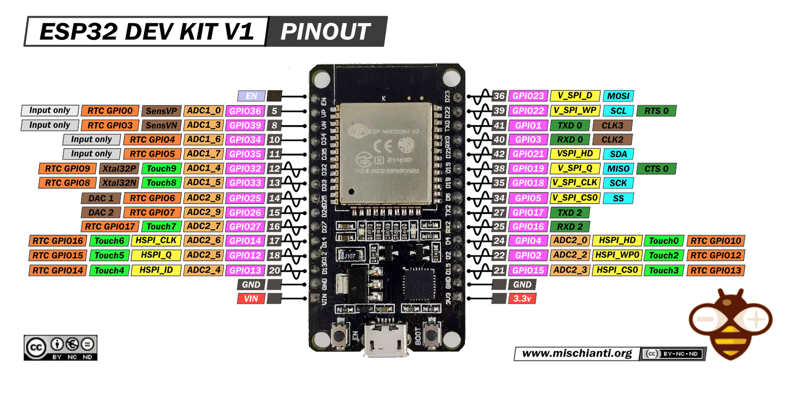
| Pin | GPIO | Labels | Status | Capabilities | Notes |
|---|---|---|---|---|---|
| 1 | - | EN | control | - | Chip enable / reset (active LOW) |
| 2 | - | GND | ground | - | Ground connection |
| 3 | - | 5V | power | - | 5V power input for the board |
| 4 | - | GND | ground | - | Ground connection |
| 5 | - | 3V33.3V | power | - | 3.3V power output |
| 6 | 1 | TX0GPIO1 | uart | - | UART0 TX - wired to the USB serial chip, avoid for general IO |
| 7 | 2 | IO2GPIO2 | strapping | adc | GPIO, ADC2, onboard blue LED, strap pin - keep floating or low at boot |
| 8 | 3 | RX0GPIO3 | uart | - | UART0 RX - wired to the USB serial chip, avoid for general IO |
| 9 | 4 | IO4GPIO4 | strapping | adc | GPIO, ADC2, touch |
| 10 | 5 | IO5GPIO5 | strapping | - | GPIO, VSPI CS (default), strap pin - outputs a PWM burst at boot |
| 11 | 12 | IO12GPIO12 | strapping | adc | GPIO, ADC2, HSPI MISO, strap pin - must NOT be high at boot or the board won't start |
| 12 | 13 | IO13GPIO13 | strapping | adc | GPIO, ADC2, HSPI MOSI, touch |
| 13 | 14 | IO14GPIO14 | strapping | adc | GPIO, ADC2, HSPI SCK, touch |
| 14 | 15 | IO15GPIO15 | strapping | adc | GPIO, ADC2, HSPI CS, strap pin - pull low at boot to silence ROM boot messages |
| 15 | 16 | RX2GPIO16 | strapping | - | GPIO, UART2 RX - free hardware serial for GPS, sensors, etc. |
| 16 | 17 | TX2GPIO17 | strapping | - | GPIO, UART2 TX - free hardware serial for GPS, sensors, etc. |
| 17 | 18 | IO18GPIO18 | safe | - | GPIO, VSPI SCK (default SPI clock) |
| 18 | 19 | IO19GPIO19 | safe | - | GPIO, VSPI MISO (default) |
| 19 | 21 | SDAGPIO21 | safe | - | GPIO, I2C SDA (default) |
| 20 | 22 | SCLGPIO22 | safe | - | GPIO, I2C SCL (default) |
| 21 | 23 | IO23GPIO23 | safe | - | GPIO, VSPI MOSI (default) |
| 22 | 25 | IO25GPIO25 | safe | adc | GPIO, ADC2, DAC1 (true analog output) |
| 23 | 26 | IO26GPIO26 | safe | adc | GPIO, ADC2, DAC2 (true analog output) |
| 24 | 27 | IO27GPIO27 | safe | adc | GPIO, ADC2, touch |
| 25 | 32 | IO32GPIO32 | safe | adc | GPIO, ADC1 (works with WiFi on), touch |
| 26 | 33 | IO33GPIO33 | safe | adc | GPIO, ADC1 (works with WiFi on), touch |
| 27 | 34 | IO34GPIO34 | strapping | adc | ADC1 - INPUT ONLY, no output driver, no internal pull-ups |
| 28 | 35 | IO35GPIO35 | strapping | adc | ADC1 - INPUT ONLY, no output driver, no internal pull-ups |
| 29 | 36 | VPGPIO36 | strapping | adc | ADC1 (VP) - INPUT ONLY, no output driver, no internal pull-ups |
| 30 | 39 | VNGPIO39 | strapping | adc | ADC1 (VN) - INPUT ONLY, no output driver, no internal pull-ups |
Start with these
10 pins with no boot or system involvementFreely assignable - no strapping, flash, USB or JTAG duties. Ideal first picks for buttons, sensors and LEDs.
Fine - with a little care
sampled at boot or shared with debug/serial| Pin | Label | What to know | Role |
|---|---|---|---|
| IO2 | GPIO2 | If driven HIGH on reset (while IO0 is LOW), selects an unsupported SDIO boot mode, causing boot failure. | Strapping |
| IO4 | GPIO4 | Sampled at reset for boot config; should not be driven at boot (affects boot mode timing). | Strapping |
| IO5 | GPIO5 | Must be HIGH during boot; if pulled LOW at reset, alters SDIO slave timing and may prevent normal boot. | Strapping |
| IO12 | MTDI (GPIO12) | Keep LOW during boot (internal PD); pulling HIGH at reset selects 1.8V flash mode, causing flash brownout if 3.3V flash is used. | Strapping |
| IO13 | MTCK (GPIO13) | Used for JTAG debugging (TCK); avoid using as GPIO if JTAG is needed. | Other |
| IO14 | MTMS (GPIO14) | Used for JTAG debugging (TMS); driving it as GPIO may interfere with JTAG or produce spurious signals at boot. | Other |
| IO15 | MTDO (GPIO15) | Keep HIGH during boot (internal PU); if LOW on reset, bootloader log is silenced and boot mode may change. | Strapping |
| RX2 | GPIO16 | Wired to the memory die on PSRAM-equipped modules (WROVER, PICO-V3-02) and on in-package-memory chip variants (U4WDH, D0WDRH2-V3); an ordinary GPIO on a plain WROOM-32. | PSRAM |
| TX2 | GPIO17 | Wired to the memory die on PSRAM-equipped modules (WROVER, PICO-V3-02) and on in-package-memory chip variants (U4WDH, D0WDRH2-V3); an ordinary GPIO on a plain WROOM-32. | PSRAM |
| IO34 | GPIO34 | Cannot be used as output (no drive capability); only suitable for analog/digital input. | Other |
| IO35 | GPIO35 | Cannot be used as output; only suitable for input. | Other |
| VP | GPIO36 (SENSOR_VP) | Cannot be used as output; only suitable for input (e.g., analog read). | Other |
| VN | GPIO39 (SENSOR_VN) | Cannot be used as output; only suitable for input. | Other |
Only if you know the tricks
wired to flash or USB - expect a fight| Pin | Label | What to know | Role |
|---|---|---|---|
| TX0 | U0TXD (GPIO1) | Connected to on-board USB-UART for uploading and logs; drives serial output at boot, so using as GPIO can disrupt programming or console. | USB |
| RX0 | U0RXD (GPIO3) | Used for receiving data from USB-UART (programming); also pulled HIGH at boot for console communication, so using as GPIO can disrupt uploads. | USB |
Pinout notes Across 30 pins, the DOIT ESP32 DEVKIT V1 exposes 25 GPIO plus GND, 5V and 3V3 for power. Peripheral wiring is straightforward: I²C is mapped to SDA on GPIO21…
Across 30 pins, the DOIT ESP32 DEVKIT V1 exposes 25 GPIO plus GND, 5V and 3V3 for power.
Peripheral wiring is straightforward: I²C is mapped to SDA on GPIO21 and SCL on GPIO22.
Beyond plain digital I/O you get 15 ADC-capable pins for sensors and battery monitoring.
13 of the exposed pins carry boot-time or system duties on the ESP32 (IO2, IO4, IO5 and 10 more) - check the guidance above before wiring anything to them. IO18, IO19, SDA, SCL and 6 more are free of any such role - the safest first picks.
The DOIT ESP32 DEVKIT V1 pinout exposes nearly the entire feature set of the ESP32 on two easy-to-breadboard rows of 15 pins each.
Power rails include VIN (5 V) for USB or external input, a regulated 3V3 output, and several GND pins for solid reference.
Serial I/O: TX0 (GPIO1) and RX0 (GPIO3) link to the CP2102 for USB programming, while TX2 (GPIO17) and RX2 (GPIO16) give you a second hardware UART for sensors or GPS modules.
I²C defaults to SDA (GPIO21) and SCL (GPIO22), but any open GPIO can be reassigned in software.
SPI comes in two flavors: the default VSPI bus (MOSI GPIO23, MISO GPIO19, SCK GPIO18, CS GPIO5) and an alternate HSPI bus on GPIO12-GPIO15 for additional devices.
Analog & touch: Eight ADC1 channels reside on GPIO32-GPIO39, usable even when Wi-Fi is active. Extra ADC2 channels (e.g., GPIO0, 2, 4, 12-15, 25-27) are shared with Wi-Fi. Dual 8-bit DAC outputs sit on GPIO25 and GPIO26. Many of these pads double as capacitive-touch sensors for sleek, button-free interfaces.
Every GPIO can source PWM signals for LED dimming or motor control. Keep an eye on boot-strap pins-GPIO0, GPIO2, and GPIO15-which must be held in the correct state (usually HIGH) during reset for normal startup.
From robust power handling to multiple high-speed buses, the DOIT ESP32 DEVKIT V1 pinout gives makers and professionals alike the flexibility to build anything from simple sensor nodes to fully fledged connected products-all on a compact, breadboard-friendly board.
Getting started
flash your first firmware in ~2 minutesBoard: ESP32 Dev Module Flash Size: 4MB (32Mb) Flash Mode: DIO Partition Scheme: Default 4MB with spiffs (1.2MB APP/1.5MB SPIFFS) Upload Speed: 921600
// toggle GPIO18 - wire an LED and resistor to it
void setup() {
  pinMode(18, OUTPUT);
}
void loop() {
  digitalWrite(18, HIGH); delay(500);
  digitalWrite(18, LOW);  delay(500);
}[env:esp32doit-devkit-v1]
platform = espressif32
board = esp32dev
framework = arduino
monitor_speed = 115200
upload_speed = 921600esp32dev - or type it after board =.esp32:
board: esp32dev
variant: esp32
framework:
type: esp-idf
# blink - GPIO18
output:
- platform: gpio
pin: 18
id: led_out
light:
- platform: binary
name: "LED"
output: led_outesp32dev (same ids as PlatformIO).esptool.py --chip esp32 --port /dev/ttyACM0 \
--baud 921600 write_flash 0x1000 firmware.bin--port = your /dev/tty* (macOS/Linux) or COMx (Windows).Good to know
board-specific quirks worth 60 seconds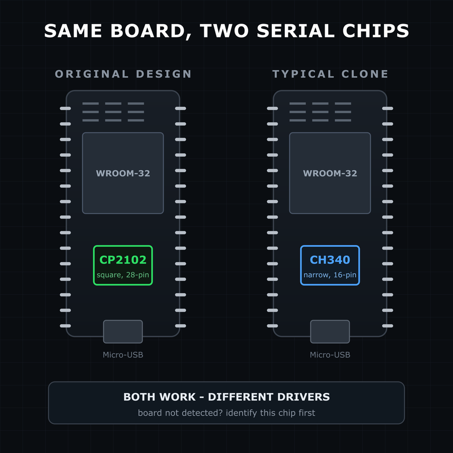
DOIT published the original DevKit V1 design, but the board long ago outgrew its maker: nearly every "ESP32 DevKit V1" sold today is an unbranded clone - same ESP32-WROOM-32 module, same 30-pin layout, same pinout. For practical purposes they're interchangeable, and everything on this page applies to all of them. The one difference that actually matters day-to-day is the USB-to-serial chip next to the Micro-USB…
DOIT published the original DevKit V1 design, but the board long ago outgrew its maker: nearly every "ESP32 DevKit V1" sold today is an unbranded clone - same ESP32-WROOM-32 module, same 30-pin layout, same pinout. For practical purposes they're interchangeable, and everything on this page applies to all of them.
The one difference that actually matters day-to-day is the USB-to-serial chip next to the Micro-USB port: the original design uses a CP2102, while the cheapest clones ship a CH340. Both work - they just need different drivers, so if your board isn't detected, identify the chip first. Our CH340 vs CP2102 guide covers telling them apart.
Unsure exactly which variant you own? The 30-pin generic clone guide walks through the common variations - board width, chip markings, and pin labels.
The ESP32 chip itself can deep-sleep at around 10 µA - but this board can't. Measurements on DevKit-style boards consistently land around 5-10 mA in deep sleep, three orders of magnitude higher, because three components stay awake no matter what your firmware does: the AMS1117 regulator, with roughly 5 mA quiescent draw on its own, the USB-serial chip, powered even with no cable data, the power LED, wired straight…
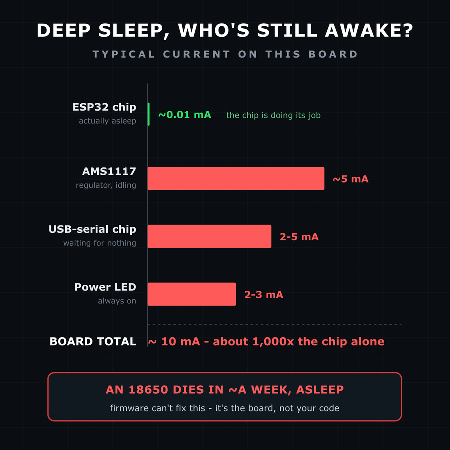
The ESP32 chip itself can deep-sleep at around 10 µA - but this board can't. Measurements on DevKit-style boards consistently land around 5-10 mA in deep sleep, three orders of magnitude higher, because three components stay awake no matter what your firmware does:
- the AMS1117 regulator, with roughly 5 mA quiescent draw on its own,
- the USB-serial chip, powered even with no cable data,
- the power LED, wired straight to the 3.3 V rail.
This measurement write-up breaks down the numbers, and this teardown confirms them component by component.
At ~10 mA of sleep current, an 18650 cell dies in about a week doing nothing. This board is great on the bench; for battery projects pick a board designed for low quiescent draw, or be prepared to desolder the LED and regulator.
If the serial monitor shows Brownout detector was triggered in a reset loop, the board isn't broken and your code probably isn't either. WiFi transmit bursts draw brief spikes of current, and if the supply voltage dips below the ~2.4 V brownout threshold even for an instant, the chip resets. The usual culprits are thin or long USB cables, weak USB ports, and unpowered hubs. Work down this list before touching the…
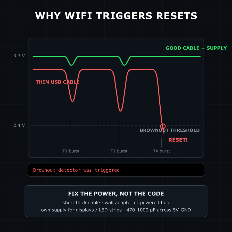
If the serial monitor shows Brownout detector was triggered in a reset loop, the board isn't broken and your code probably isn't either. WiFi transmit bursts draw brief spikes of current, and if the supply voltage dips below the ~2.4 V brownout threshold even for an instant, the chip resets. The usual culprits are thin or long USB cables, weak USB ports, and unpowered hubs.
Work down this list before touching the code:
- swap to a short, known-good USB cable, straight into the computer or a wall adapter,
- if peripherals share the 5 V rail (displays, LED strips, servos), give them their own supply,
- a 470-1000 µF capacitor across 5V/GND smooths the spikes on stubborn setups.
You'll find advice online to disable the brownout detector in software. That hides the symptom instead of fixing the supply - the chip will just misbehave in less obvious ways.
Specifications
ESP32 · 51.45 × 23.37 mm · vs other ESP32 chips →About this board
Inside sits the ESP32 - a dual-core Xtensa with both Bluetooth Classic and BLE.
At $5.00 it's cheaper than most ESP32 boards, which usually run around $20.
Around the module: status LEDs (Power, Blue (GPIO2)) and Reset/Boot buttons.
Not sure if this is your board? Or you have a similar clone?
Check out the ESP32 30-Pin Generic Clone Guide - it covers all the common variations and helps you identify which board you actually have!
The ESP32 DevKit V1 is the board most people mean when they say "an ESP32": a slim, 30-pin development board built around the proven Espressif ESP32-WROOM-32 module, with dual-core processing, Wi-Fi 802.11 b/g/n and Bluetooth 4.2 (BR/EDR + BLE). The design was originally published by DOIT, but boards sold under this name today are overwhelmingly unbranded clones - same layout, same module, same pinout. Everything on this page applies to them all, whatever logo (or none) is on yours.
An on-board CP2102 USB-to-UART converter (CH340 on many clones) and auto-reset circuitry let you plug in, program, and debug over Micro-USB with zero fuss.
Power options are flexible: feed the board via
VIN (5 V), the Micro-USB port, or tap the regulated 3V3 rail for low-power projects. A high-efficiency LDO keeps everything stable.Development conveniences include a dedicated EN (reset) button and a BOOT (IO0) button for easy firmware flashing and download-mode entry.
With rich peripherals-ADC, DAC, PWM, capacitive-touch, I²C, SPI, UART and more-the ESP32 DevKit V1 is ready to drive sensors, displays, motors, or anything your next connected gadget requires.
Where to buy
prices are typical street pricesResources
Similar boards


