
How to read an ESP32 pinout diagram
Every colour, shape and badge on an ESPboards pinout sheet, explained: what it is, why it matters on an ESP32, and what you would actually do with it.
1Anatomy of the diagram
Every sheet has the same five parts. Once you can find them on one board, you can read all of them.
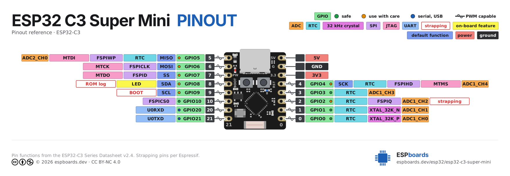
- The pin number boxThe dark square nearest the board is the header position, counted from pin 1 - the same number the Full table tab uses. It is not the GPIO number; that comes next.
- The GPIO chip and its dotThe green chip names the pin as the chip sees it - GPIO7 is what you type in code. The small dot on it says how freely you can use it. Read the GPIO chip ↓
- Function chips, reading outwardEverything the pin can do, one chip per function, nearest the board first. The colour says which subsystem; the shape says what kind of claim it is. Read the shapes ↓
- The keyTop right, under the board's name. It lists only what this board actually draws, so a short key means a simple board, not a missing one. Every entry in it has a section on this page.
- The footerThe datasheet the sheet was drawn from, the licence, and the board's page on this site. The datasheet is the source of every pin function above it; the board's own entry is the source of the names on the silkscreen.
2The GPIO chip and its dot
Most rows start with a green chip. It is the most-read thing on the sheet, and the dot on it is the single most useful fact about the pin.
GPIO - a general-purpose pin
#gpioA general-purpose input/output: a pin you can program to read a switch, drive an LED, or carry a bus. The number is the GPIO number, which is what every framework wants - digitalWrite(7, HIGH), Pin(7) in MicroPython, GPIO7 in ESPHome. It is the chip's numbering, so it is the same on every board that uses that chip.
A row with no green chip is not a GPIO at all: it is power, ground, or a control pin like EN, and it has no number to type.
Green dot - safe to use
#safeNothing happens on this pin at boot and no on-chip system needs it. Wire anything to it. On the board page: Start with these.
Amber dot - use with care
#warnThe pin works, but one of the chip's caution notes names it: a strapping pin, a JTAG line, a pin whose level at reset matters. Read the row's other chips before you commit. On the board page: Fine - with a little care.
Blue dot - serial or USB by default
#sysThis pin carries the board's link to your computer - the UART0 TX/RX pair on a classic ESP32, or the USB D-/D+ pair on a C3, S3 or C6. You can use it, but you lose uploads or the serial monitor while you do. On the board page: Only if you know the tricks.
Wave on the leader - PWM capable
#pwmThe line from the board to the chips carries a small wave when the pin can drive a PWM output: switching on and off fast enough to look like a level - what dims an LED, sets a servo angle or a motor speed. On an ESP32 that is every GPIO except the input-only ones (GPIO34-39 on the classic chip), so the wave mostly tells you where PWM is not.
// arduino-esp32 3.x: attach, then write
ledcAttach(25, 5000, 8);   // 5 kHz, 8-bit
ledcWrite(25, 128); // half of 2553What a chip's shape tells you
Colour says which subsystem a chip belongs to. The chip's treatment says what kind of claim it is making - and that is a separate question.
Solid - a function you can use
The pin offers this. Take it if you want it, ignore it if you do not; nothing about the pin changes either way.
Outlined - a condition, read it first
Not a feature: something you need to know before you wire to this pin. The chip is hollow because it is a note about the pin, not a thing the pin does.
Hatched - not available to you
The chip is already using this pin internally, every microsecond it runs. There is no condition to satisfy; there is just nothing here for you.
Light grey - a name, not a claim
What the board or its Arduino core calls this pin. Useful for matching a tutorial, but it says nothing about what the pin can do - the coloured chips beside it do.
4Every badge
In the order the key lists them. Pin numbers below are for the classic ESP32 unless a chip is named; the sheet for your board has the right ones.
ADC - analog-to-digital converter
#adcReads a voltage instead of just on or off. A plain digital pin can tell you "this is connected to 3.3 V"; an ADC pin tells you it is at 1.87 V. The ESP32 reads 12 bits, so you get a number from 0 to 4095 across 0 to 3.3 V.
The badge names a channel, like ADC1_CH6, and the prefix matters more than the number. On the classic ESP32, ADC2 belongs to the Wi-Fi radio: while Wi-Fi is on, ADC2 reads fail. If your project has Wi-Fi, stay on ADC1 - GPIO32 to 39. The S3 splits its pins the same way and the same Wi-Fi rule applies there. On the C3 it is worse: Espressif dropped ADC2 from the one-shot driver altogether, because the readings are not stable. The C6 has ADC1 only, so the question never comes up.
Classic ESP32: ADC1 on GPIO32-39 · ADC2 on GPIO0, 2, 4, 12-15, 25-27
// ADC1, so it keeps working with Wi-Fi up
int raw = analogRead(34);          // 0 .. 4095
float volts = raw * 3.3 / 4095;
Going further: Voltage dividers on ESP32 GPIO pins, and where they go wrong →
Touch sensor, and DAC
#touchOne colour for two things the classic ESP32 does with analog signals. The chip's text says which.Touch: the pin measures its own capacitance, and a fingertip changes it. A bare wire, a strip of copper tape or a pad on the PCB becomes a button with no button. DAC: the opposite of the ADC - writes a real voltage out, 8 bits, 0 to 3.3 V.
Both are classic-ESP32 things. It has ten touch channels (T0 to T9) and two DAC pins (GPIO25 and 26); the S3 has fourteen touch channels and no DAC; the C3 and C6 have neither, which is why these chips are rare on the newer boards. Touch also works as a deep-sleep wake source, with nothing but a wire.
Classic ESP32: touch on GPIO0, 2, 4, 12-15, 27, 32, 33 · DAC on GPIO25, 26
// T0 is GPIO4 on the classic ESP32; smaller reading = touched
int t = touchRead(T0);RTC - the low-power domain
#rtcNot a clock. On an ESP32, "RTC" is the small part of the chip that stays powered in deep sleep, and an RTC GPIO is a pin that belongs to it. Everything else on the chip is off in deep sleep - which is how a board gets from tens of milliamps to tens of microamps.
That makes these the only pins that can wake the chip from deep sleep - a button, a motion sensor, a reed switch - and, on the chips that have an ultra-low-power coprocessor, the only pins it can read while the main cores sleep. The classic ESP32 and the S3 have one; the C6 calls its one the LP core, which is why its RTC pins are named LP_GPIO; the C3 has none. If your project runs on a battery, the wake input has to be one of these.
Classic ESP32: GPIO0, 2, 4, 12-15, 25-27, 32-39 · C3: GPIO0-5 · C6: GPIO0-7 · S3: GPIO0-21
// wake when GPIO33 (an RTC pin) is pulled low, then sleep
esp_sleep_enable_ext0_wakeup(GPIO_NUM_33, 0);
esp_deep_sleep_start();32 kHz crystal pads
#xtalThe two pins an external 32.768 kHz crystal can attach to - the same kind of crystal that keeps time in a wristwatch. With one fitted, the chip keeps accurate time through deep sleep and can wake on a schedule that does not drift.
Almost no development board fits one, so on almost every board these are ordinary GPIOs. The sheet paints them anyway, for the one board in fifty that does - if yours has a tiny metal cylinder near these pins, they are taken. It is also why these two are always RTC pins as well.
Classic ESP32: GPIO32, 33 · C3 and C6: GPIO0, 1 · S3: GPIO15, 16
SPI - the fast four-wire bus
#spiA bus for the parts that move a lot of data: displays, SD cards, radio modules, flash chips. Four wires: a clock (SCK / CLK), data out (MOSI / D), data in (MISO / Q), and a chip select (CS / SS) per device, so several devices can share the same three lines.
An ESP32 can route SPI to almost any pin, so why name these? Because the named ones are the bus's native pins, wired straight through the IO MUX - the fastest path, and the one a display driver assumes. The classic ESP32 has two user buses, VSPI and HSPI; the newer chips call theirs FSPI.
Classic ESP32: VSPI on GPIO18 (CLK), 19 (MISO), 23 (MOSI), 5 (CS) · HSPI on GPIO14, 12, 13, 15
// the VSPI pins: SCK, MISO, MOSI, SS
SPI.begin(18, 19, 23, 5);SDIO - the SD/MMC bus
#sdioThe bus SD cards were designed for: a clock, a command line, and four data lines at once, where SPI moves one bit at a time. It appears only on boards that route it to the header and name it - the XIAO ESP32C6, for one, where it is the chip's slave port rather than a card reader.
Its own colour, and not the SPI purple, because it sits right beside SPI pins on those boards and it is a different bus. If you are not using it, these are ordinary GPIOs. Which way it runs depends on the chip: the classic ESP32 has both an SD host and an SDIO slave, while the C6 has a slave controller only - another processor drives the bus and talks to the C6 over it, so these pins are not an SD card reader on a C6 board.
JTAG - the hardware debug port
#jtagFour pins a hardware debugger attaches to - the kind that lets you pause the running chip, step through code and read variables, rather than sprinkling Serial.println. The chips are named MTDI, MTCK, MTMS and MTDO.
Unless you own a JTAG probe and have set one up, they are ordinary GPIOs, and most people use them that way. The catch is the classic ESP32's MTDI, GPIO12: it is also a strapping pin that sets the flash voltage, which is a separate problem from JTAG. The C3, S3 and C6 also debug over their USB port, so on those you can leave these pins free and still use a debugger.
Classic ESP32: GPIO12-15 · C3: GPIO4-7 · S3: GPIO39-42 · C6: GPIO4-7
UART, I2C and USB - the serial links
#uartOne colour: these chips are the names of serial signals. The dot on the GPIO chip says whether the pin is spoken for.UART is plain two-wire serial: TX out, RX in. Every ESP32 has a UART0 that is the link to your computer on boards with a USB-serial chip - that is the blue dot. The other UARTs (UART1, UART2) are yours, for a GPS, a modem, another board. USB on the C3, S3 and C6 is a native pair, D- and D+, that does upload, serial monitor and debugging all at once - the blue dot again. I2C is the two-wire sensor bus - SDA for data, SCL for clock - and it costs you nothing by default: it is just two pins you pick.
Which pins these land on is the thing that changes most between boards: a classic DevKit talks to your computer over GPIO1 and 3 through a USB-serial chip, a C3 or S3 board over its native USB pair, and a board with both may expose either. The sheet names the signal so you can tell which link a pin belongs to before you take it.
Classic ESP32: UART0 on GPIO1 (TX), 3 (RX) · UART2 pads on GPIO16, 17 · C3: USB on GPIO18, 19 · S3: USB on GPIO19, 20 · C6: USB on GPIO12, 13
// a second serial port on two ordinary pins: RX, TX
Serial1.begin(115200, SERIAL_8N1, 16, 17);Flash and PSRAM - taken by the module
#flashThe pins wired to the flash chip inside the module - where your program lives - and, on boards that have it, the PSRAM. The chip reads code from flash every microsecond it runs, over exactly these lines.
There is no trick and no condition: touch one of these and the program stops, corrupts, or the board resets in a loop until you re-flash it. Most boards do not even route them to the header. The ones that do - some 38-pin DevKits with GPIO6-11 on the edge - are the reason this badge exists.
Classic ESP32: GPIO6-11 · C3: GPIO11-17 · S3: GPIO26-32 (33-37 too on octal-PSRAM modules) · C6: GPIO24-30
Strapping pin
#strappingAn outlined badge, so it is a condition, not a feature. In the instant the chip comes out of reset, it reads the level on a handful of pins to decide how to start: run the program, or wait for an upload; what voltage the flash runs at; whether to print boot messages. After that instant they are ordinary GPIOs.
Which is why the trouble is always one-directional: whatever you attach must not be holding the pin at the wrong level during reset. A sensor that pulls GPIO0 low at power-up does not break the sensor - it stops the board booting at all, with no error to read. Pulling the classic ESP32's GPIO12 high at reset tells it the flash is 1.8 V, and a 3.3 V module then fails to start.
Classic ESP32: GPIO0 (BOOT), 2, 5, 12, 15 · C3: GPIO2, 8, 9 (BOOT) · S3: GPIO0 (BOOT), 3, 45, 46 · C6: GPIO4, 5, 8, 9 (BOOT)
Going further: ESP32 strapping pins: the complete list for every chip → · ESP32 not powering or booting up →
On-board feature
#onboardThe pin is wired to a part on the board: the blue LED, an RGB LED, the BOOT button, a battery-voltage divider, a display backlight. The chip names the part. The same colour is used for a name the board's maker gave a pin it wired somewhere - 485_EN, SD_CS, CFG - because that is the same kind of fact.
It is a solid chip because you can use it - blink the LED, read the button - but the pin is not entirely free: an LED loads it, a button pulls it. If you also wire something else there, both have to agree.
// GPIO2 drives the on-board LED on most DevKits
pinMode(2, OUTPUT);
digitalWrite(2, HIGH);Default function
#fndefWhere a bus lands when you configure nothing. SPI.begin() with no arguments, Wire.begin(), plain Serial: each picks a set of pins, and these chips - SCK, MISO, MOSI, SS, SDA, SCL, TX, RX - mark them. Libraries and tutorials assume them.
They are one colour, and not the colour of their bus, because it is one idea: "this is where it goes unless you say otherwise". Wire a breakout to these and you can skip the pin arguments; wire it anywhere else and you pass pins - which works fine, but is the step every "it does not respond" question turns out to have missed.
// no pin arguments: the core uses this board's default pins
SPI.begin();
Wire.begin();Arduino name
#arduinoThe name the board's Arduino core defines for the pin - D5, A0, LED_BUILTIN - and what you type in a sketch written for that board. On a XIAO ESP32C3, D5 and 7 are the same pin; the sheet prints both so you can translate.
A light chip because it is only a name: it says nothing about what the pin can do. It also exists only in Arduino - ESPHome and MicroPython want the GPIO number, and so does any library that was not written for your exact board. When a tutorial for a different board says D5, it means that board's D5.
// the name comes from the board definition (here the XIAO ESP32C3)
pinMode(D5, INPUT_PULLUP);Not connected
#ncA header position with nothing behind it: the hole is there, the copper is not. Common on boards that share a footprint with a bigger sibling, or a layout that left room for a feature that never shipped.
Hollow, because there is nothing to draw. It is harmless - wire to it and nothing happens - but do not count it when you tally the GPIOs a board gives you.
Power
#powerThe board's supply pins. 5V (also VIN, VBUS) is the USB rail: on most boards it is both an input, to power the board without USB, and an output, the raw 5 V straight from the cable. 3V3 is the output of the board's regulator - the voltage the ESP32 actually runs on. VBAT, where it exists, is a battery input with a charger behind it.
Two rules cover most accidents. The 3V3 pin has limited spare current - a small sensor is fine, an LED strip or a motor is not; those go on 5V or their own supply. And no GPIO tolerates 5 V: a 5 V signal into a pin needs a divider or a level shifter first.
Going further: ESP32 not powering or booting up →
Ground
#groundThe return path and the zero every other voltage is measured from. Every GND pin on the board is the same net; there is no "better" one, only the nearest one.
Everything you connect to the board must share its ground - a sensor on its own supply, a second board, a motor driver. A missing ground wire is the most common cause of readings that drift, serial output that is garbage, and parts that work only when you touch them.
EN / reset
#controlEN (enable, also CHIP_PU or RST) is the chip's reset line: pull it low and the ESP32 stops; release it and it boots from scratch. The RESET button on the board does exactly that. Not a GPIO - you cannot read or drive it from code.
It is on the header for two reasons: so another controller can reset the board, and so you can fix the one classic fault - some boards fail to auto-reset for uploads, and a small capacitor (1 to 10 uF) from EN to GND cures it.
Going further: ESP32 auto-reset failure during upload, and the circuit behind it →
5Where these facts come from
Every pin function on a sheet is transcribed from the chip's datasheet - the exact document and table are named in the sheet's footer - into a per-chip table this site maintains. The names on the silkscreen, the on-board parts and which pins reach the header come from the board's own entry on this site, checked against the maker's documentation.
Every board we have drawn shows its sheet on its own page, in high resolution: browse the ESP32 boards →