
LilyGo T-Embed CC1101
An ESP32-S3 development board with integrated CC1101 RF module, suitable for sub-1GHz wireless communication projects.

LilyGo T-Embed CC1101 Pinout
8 pins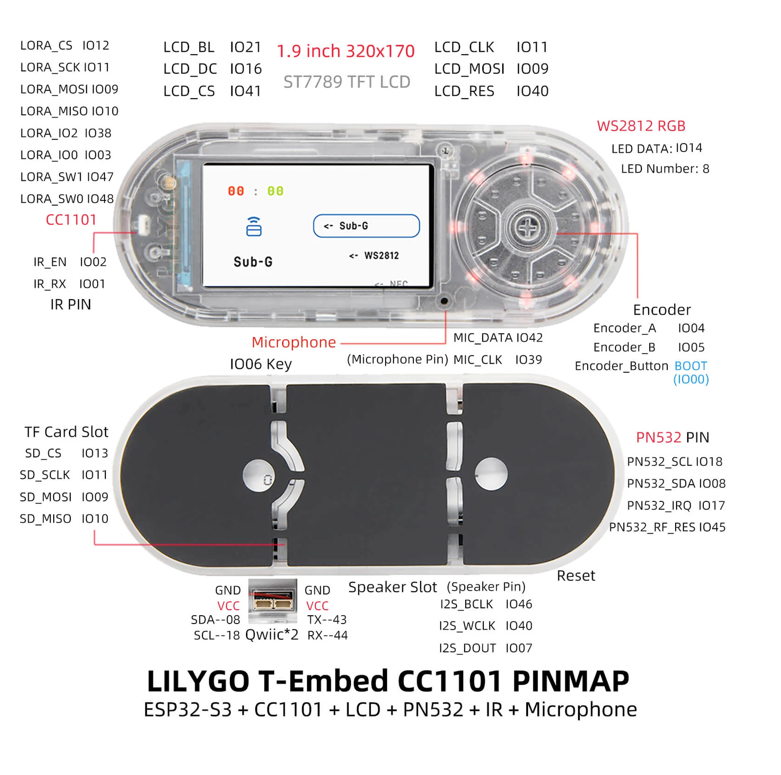
| Pin | GPIO | Labels | Status | Capabilities | Notes |
|---|---|---|---|---|---|
| 1 | 8 | SDAIO8 | safe | adc · touch · i2c | I2C/QWIIC extension connector SDA; shared with onboard PN532, BQ27220 and BQ25896 |
| 2 | 18 | SCLIO18 | safe | adc · i2c | I2C/QWIIC extension connector SCL; shared with onboard PN532, BQ27220 and BQ25896 |
| 3 | - | 3V3 | power | - | 3.3V output on the I2C/QWIIC extension connector |
| 4 | - | GND | ground | - | Ground on the I2C/QWIIC extension connector |
| 5 | 43 | TXDU0TXD | uart | uart | UART extension connector TX (U0TXD); reused as nRF24 CE in the extend example |
| 6 | 44 | RXDU0RXD | uart | uart | UART extension connector RX (U0RXD); reused as nRF24 CS in the extend example |
| 7 | - | 3V3 | power | - | 3.3V output on the UART extension connector |
| 8 | - | GND | ground | - | Ground on the UART extension connector |
Start with these
2 pins with no boot or system involvementFreely assignable - no strapping, flash, USB or JTAG duties. Ideal first picks for buttons, sensors and LEDs.
Fine - with a little care
2 pins · 2 things to knowTXDGPIO43 UART0 transmit pin (U0TXD), default serial console TX UART
Used for bootloader output and UART console logs. If repurposed, you will lose the default serial output (and programming via UART0).
RXDGPIO44 UART0 receive pin (U0RXD), default serial console RX UART
Used for bootloader input (download mode via serial). If repurposed, you cannot use the default UART0 download mode for programming the chip.
The LilyGo T-Embed CC1101 pinout brings out 8 pins - 4 usable GPIO alongside the 3V3 and GND power rails.
Peripheral wiring is straightforward: I²C is mapped to SDA on GPIO8 and SCL on GPIO18.
Beyond plain digital I/O you get 2 ADC-capable pins for sensors and battery monitoring and 1 capacitive-touch inputs.
2 of the exposed pins carry boot-time or system duties on the ESP32-S3 (TXD and RXD) - check the guidance above before wiring anything to them. SDA and SCL are free of any such role - the safest first picks.
Getting started
flash your first firmware in ~2 minutesBoard: ESP32S3 Dev Module USB CDC On Boot: Enabled Flash Size: 16MB (128Mb) Flash Mode: DIO PSRAM: OPI PSRAM Partition Scheme: 16M Flash (3MB APP/9.9MB FATFS) Upload Speed: 921600
// toggle GPIO8 - wire an LED and resistor to it
void setup() {
  pinMode(8, OUTPUT);
}
void loop() {
  digitalWrite(8, HIGH); delay(500);
  digitalWrite(8, LOW);  delay(500);
}[env:lilygo_t_embed_cc1101]
platform = espressif32
board = esp32-s3-devkitc-1
framework = arduino
monitor_speed = 115200
upload_speed = 921600
board_build.arduino.memory_type = qio_opi
build_flags = -DBOARD_HAS_PSRAMesp32-s3-devkitc-1 - or type it after board =.esp32:
board: esp32-s3-devkitc-1
variant: esp32s3
framework:
type: esp-idf
psram:
mode: octal
speed: 80MHz
# blink - GPIO8
output:
- platform: gpio
pin: 8
id: led_out
light:
- platform: binary
name: "LED"
output: led_outesp32-s3-devkitc-1 (same ids as PlatformIO).esptool.py --chip esp32s3 --port /dev/ttyACM0 \
--baud 921600 write_flash 0x0 firmware.bin--port = your /dev/tty* (macOS/Linux) or COMx (Windows).Specifications
ESP32-S3 · 97.5 × 39 mm · vs other ESP32 chips →Dimensions
About this board
Inside sits the ESP32-S3 - a dual-core Xtensa with vector extensions suited to AI workloads.
At $45.99 it's on the expensive side for an ESP32-S3 board - most land around $29.
Only 4 GPIO are broken out, where most ESP32-S3 boards manage about 22 - worth checking the pinout covers what you need.
Around the module: 8MB (OPI) PSRAM, an IPS LCD 1.9" 170x320 display, a microSD slot, a microphone, a speaker, an addressable RGB LED (GPIO14), an IR transceiver, a battery fuel gauge (BQ27220), an NFC/RFID reader (PN532), a rotary encoder, battery charging (BQ25896) via JST-GH 1.25mm and Reset/Boot buttons.
It flashes over native USB - no serial-converter driver needed, which isn't a given among ESP32-S3 boards.
The LilyGo T-Embed CC1101 is an advanced development board featuring an ESP32-S3 microcontroller with integrated WiFi and Bluetooth 5 capabilities. It includes the CC1101 RF transceiver, enabling sub-1GHz wireless communication, ideal for IoT applications requiring long-range and low-power connectivity.
- CC1101 sub-1GHz RF transceiver (315/433/868/915 MHz)
- 8x addressable WS2812 RGB LEDs on GPIO14
- 1300mAh Li-Po battery included
Where to buy
prices are typical street pricesResources
Similar boards

