
LilyGo T-Watch S3
A smartwatch development platform based on ESP32-S3, suitable for wearable applications and prototyping.

Pinout
4 pins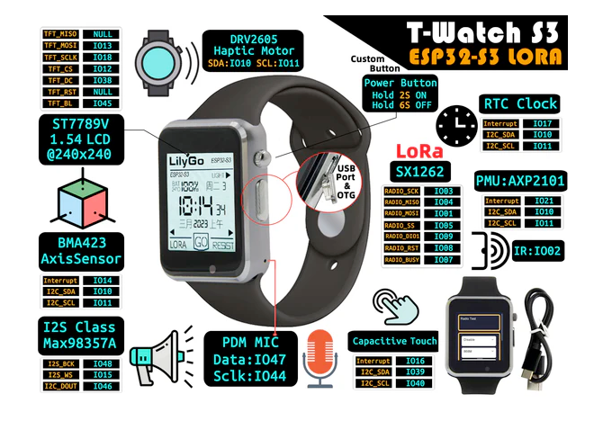
| Pin | GPIO | Labels | Status | Capabilities | Notes |
|---|---|---|---|---|---|
| 1 | - | 5VVBUS | usb | - | USB VBUS (5V) on the Micro-USB port. Charging and programming only; LilyGo states it has no external power supply function, so it cannot source 5V out. |
| 2 | - | GND | ground | - | Ground, available on the Micro-USB port. |
| 3 | 20 | D+USB_D+ | usb | - | Native USB D+ on the Micro-USB port (ESP32-S3 built-in USB, fixed to GPIO20). |
| 4 | 19 | D-USB_D- | usb | - | Native USB D- on the Micro-USB port (ESP32-S3 built-in USB, fixed to GPIO19). |
Only if you know the tricks
wired to flash or USB - expect a fight| Pin | Label | What to know | Role |
|---|---|---|---|
| D+ | USB_D+ | By default connected to the on-chip USB Serial/JTAG controller. Using it as general GPIO without reconfiguring IO MUX will interfere with USB functionality. | USB |
| D- | USB_D- | By default connected to the on-chip USB Serial/JTAG controller. Using it as general GPIO without reconfiguring IO MUX will interfere with USB functionality. | USB |
Pinout notes The LilyGo T-Watch S3 pinout brings out 4 pins - 0 usable GPIO alongside the GND power rails.
The LilyGo T-Watch S3 pinout brings out 4 pins - 0 usable GPIO alongside the GND power rails.
Getting started
flash your first firmware in ~2 minutesBoard: ESP32S3 Dev Module USB CDC On Boot: Enabled Flash Size: 16MB (128Mb) Flash Mode: DIO PSRAM: OPI PSRAM Partition Scheme: 16M Flash (3MB APP/9.9MB FATFS) Upload Speed: 921600
// toggle GPIO8 - wire an LED and resistor to it
void setup() {
  pinMode(8, OUTPUT);
}
void loop() {
  digitalWrite(8, HIGH); delay(500);
  digitalWrite(8, LOW);  delay(500);
}[env:lilygo_t_watch_s3]
platform = espressif32
board = esp32-s3-devkitc-1
framework = arduino
monitor_speed = 115200
upload_speed = 921600
board_build.arduino.memory_type = qio_opi
build_flags = -DBOARD_HAS_PSRAMesp32-s3-devkitc-1 - or type it after board =.esp32:
board: esp32-s3-devkitc-1
variant: esp32s3
framework:
type: esp-idf
psram:
mode: octal
speed: 80MHz
# blink - GPIO8
output:
- platform: gpio
pin: 8
id: led_out
light:
- platform: binary
name: "LED"
output: led_outesp32-s3-devkitc-1 (same ids as PlatformIO).esptool.py --chip esp32s3 --port /dev/ttyACM0 \
--baud 921600 write_flash 0x0 firmware.bin--port = your /dev/tty* (macOS/Linux) or COMx (Windows).Specifications
ESP32-S3 · 51.5 × 42 mm · vs other ESP32 chips →About this board
At its core is the ESP32-S3 - a dual-core Xtensa with vector extensions suited to AI workloads.
Expect to pay about $42.98 - above the ~$29 typical for ESP32-S3 boards.
Onboard you'll find 8MB (OPI) PSRAM, an IPS LCD 1.54" 240x240 display with touch, LoRa (SX1262), a microphone (SPM1423), a speaker, an amplifier (MAX98357A), a PCF8563 RTC, a motion sensor (BMA423) and battery charging (AXP2101).
It flashes over native USB - no serial-converter driver needed, which isn't a given among ESP32-S3 boards.
The LilyGo T-Watch S3 is an ESP32-S3-powered smartwatch development kit designed for wearable applications. It features a 1.54-inch IPS LCD touch screen, a built-in rechargeable battery, and a variety of sensors, making it perfect for smart wearable projects.
With integrated WiFi 802.11 b/g/n and Bluetooth 5 (LE), it enables seamless wireless connectivity for IoT applications.
Equipped with 8MB PSRAM and 16MB Flash, the T-Watch S3 is ideal for running complex applications, including graphical interfaces and real-time monitoring.
- DRV2605 haptic motor driver with vibration feedback
- Built-in rechargeable Li-Po battery
- LoRa frequency variants available (433 / 868 / 915 MHz)
Where to buy
prices are typical street pricesResources
Similar boards

