
M5Stack Dial V1.1
ESP32-S3 smart rotary knob with 1.28" round touchscreen, encoder, RFID and buzzer - a ready-made control dial for smart home and industrial panels.

M5Stack Dial V1.1 Pinout
17 pins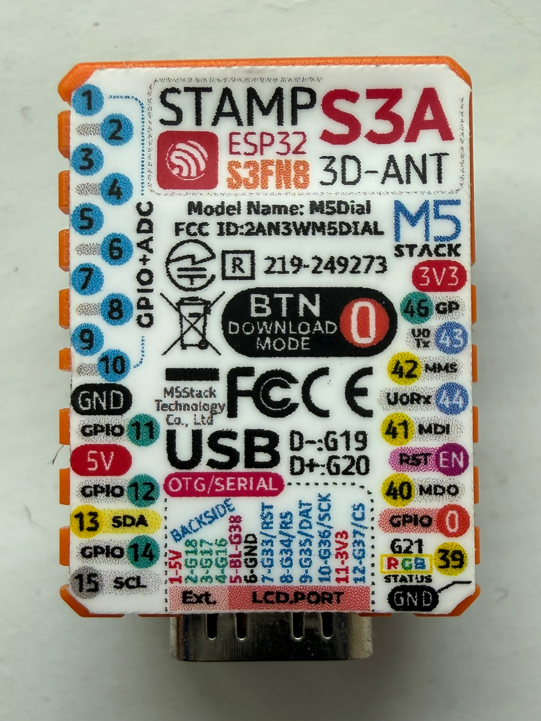
| Pin | GPIO | Labels | Status | Capabilities | Notes |
|---|---|---|---|---|---|
| 1 | 1 | G1PORT_B_IN | safe | - | |
| 2 | 2 | G2PORT_B_OUT | safe | - | |
| 3 | 3 | G3BUZZER | strapping | - | |
| 4 | 4 | G4LCD_DC | safe | - | |
| 5 | 5 | G5MOSI | safe | spi | |
| 6 | 6 | G6SCK | safe | spi | |
| 7 | 7 | G7LCD_CS | safe | - | |
| 8 | 8 | G8LCD_RST | safe | - | |
| 9 | 9 | G9LCD_BL | strapping | - | |
| 10 | 11 | G11SDA | strapping | i2c | |
| 11 | 12 | G12SCL | strapping | i2c | |
| 12 | 13 | G13PORT_A_SDA | strapping | - | |
| 13 | 15 | G15PORT_A_SCL | safe | - | |
| 14 | 40 | G40ENC_A | strapping | - | |
| 15 | 41 | G41ENC_B | strapping | - | |
| 16 | 42 | G42BUTTON | strapping | - | |
| 17 | 46 | G46HOLD | strapping | - |
Start with these
8 pins with no boot or system involvementFreely assignable - no strapping, flash, USB or JTAG duties. Ideal first picks for buttons, sensors and LEDs.
Fine - with a little care
9 pins · 6 things to knowG3GPIO3 Bootstrapping pin (controls JTAG signal source) Strapping
Sampled at reset to select JTAG interface (USB Serial/JTAG controller vs. external pins). Improper use can disable external JTAG or alter debug interface.
G9GPIO9G11GPIO11G12GPIO12G13GPIO13 General-purpose SPI2 (FSPI) IO MUX pins Other
IO MUX pin of the general-purpose SPI2 (FSPI) bus, not of the in-package flash - that sits on GPIO26-32. The datasheet lists it as a priority-2 pin ("can be freely used without restrictions"), so it is only taken if your board wires flash, an SD card or a display to FSPI.
- G9General-purpose SPI2 (FSPI) IO MUX pin - hold/data line (FSPIHD)
- G11General-purpose SPI2 (FSPI) IO MUX pin - data in (FSPID)
- G12General-purpose SPI2 (FSPI) IO MUX pin - clock (FSPICLK)
- G13General-purpose SPI2 (FSPI) IO MUX pin - data out (FSPIQ)
G40GPIO40 JTAG test data out pin (MTDO) JTAG
Default JTAG TDO output for debugging. Using it as GPIO will interfere with JTAG debugging functionality.
G41GPIO41 JTAG test data in pin (MTDI) JTAG
Default JTAG TDI input for debugging. Should be reserved for JTAG or left unused if JTAG is to remain available.
G42GPIO42 JTAG test mode select pin (MTMS) JTAG
Default JTAG TMS signal for debugging. Using this pin for other purposes will disable the JTAG interface (unless JTAG is rerouted to USB).
G46GPIO46 Bootstrapping pin (used with GPIO0 for boot mode; controls ROM log output) Strapping
Must be at a defined level during reset (with GPIO0) to select normal or download boot and UART/USB print mode. This pin is input-only (no output drive), so it should be left for its intended strapping function.
All 17 pins on the M5Stack Dial V1.1 are usable GPIO.
Peripheral wiring is straightforward: I²C is mapped to SDA on GPIO11 and SCL on GPIO12.
9 of the exposed pins carry boot-time or system duties on the ESP32-S3 (G3, G9, G11 and 6 more) - check the guidance above before wiring anything to them. G1, G2, G4, G5 and 4 more are free of any such role - the safest first picks.
Pinout notes The M5Stack Dial doesn't expose a pin header - expansion happens through its two Grove (HY2.0-4P) ports: Port A (G13 SDA / G15 SCL, I2C) and Port B (G1 input /…
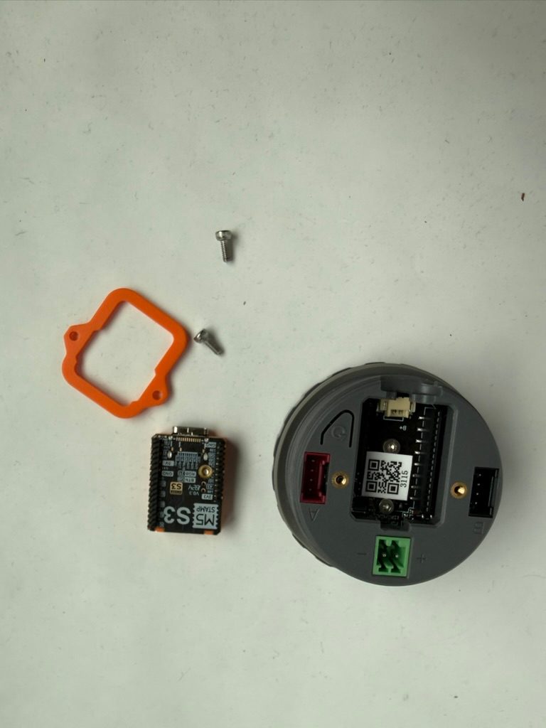
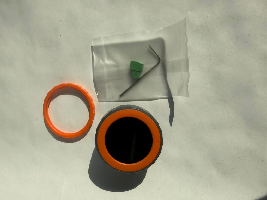
The M5Stack Dial doesn't expose a pin header - expansion happens through its two Grove (HY2.0-4P) ports: Port A (G13 SDA / G15 SCL, I2C) and Port B (G1 input / G2 output, GPIO). A 2.54-2P screw terminal for the wide-range 6-36V power input is included in the box.
Internally, the round display sits on SPI (G5 MOSI / G6 SCK, with G7 CS, G8 reset, G4 D/C and G9 backlight PWM). The touch controller, RFID reader and RTC share the internal I2C bus (G11 SDA / G12 SCL).
The rotary encoder outputs quadrature signals on G40/G41 (16 positions, 64 pulses per revolution), the buzzer is driven from G3, the front button reads on G42, and G46 acts as the power-hold pin.
Guides & tutorials

Getting started
flash your first firmware in ~2 minutesBoard: ESP32S3 Dev Module USB CDC On Boot: Enabled Flash Size: 8MB (64Mb) Flash Mode: DIO Partition Scheme: 8M with spiffs (3MB APP/1.5MB SPIFFS) Upload Speed: 921600
// toggle GPIO1 - wire an LED and resistor to it
void setup() {
  pinMode(1, OUTPUT);
}
void loop() {
  digitalWrite(1, HIGH); delay(500);
  digitalWrite(1, LOW);  delay(500);
}[env:m5stack-dial]
platform = espressif32
board = esp32-s3-devkitc-1
framework = arduino
monitor_speed = 115200
upload_speed = 921600esp32-s3-devkitc-1 - or type it after board =.esp32:
board: esp32-s3-devkitc-1
variant: esp32s3
framework:
type: esp-idf
# blink - GPIO1
output:
- platform: gpio
pin: 1
id: led_out
light:
- platform: binary
name: "LED"
output: led_outesp32-s3-devkitc-1 (same ids as PlatformIO).esptool.py --chip esp32s3 --port /dev/ttyACM0 \
--baud 921600 write_flash 0x0 firmware.bin--port = your /dev/tty* (macOS/Linux) or COMx (Windows).Good to know
board-specific quirks worth 60 seconds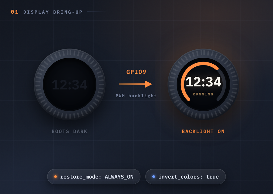
Three separate display traps, same symptom: firmware runs fine, screen shows nothing right. The backlight on GPIO9 is PWM-controlled and off at boot - the panel happily renders behind it, so no error appears anywhere. The GC9A01 panel needs color inversion enabled, otherwise every color comes out negative. And the panel is mounted rotated 180° relative to how you hold the Dial. In ESPHome: define GPIO9 as…
Three separate display traps, same symptom: firmware runs fine, screen shows nothing right. The backlight on GPIO9 is PWM-controlled and off at boot - the panel happily renders behind it, so no error appears anywhere. The GC9A01 panel needs color inversion enabled, otherwise every color comes out negative. And the panel is mounted rotated 180° relative to how you hold the Dial.
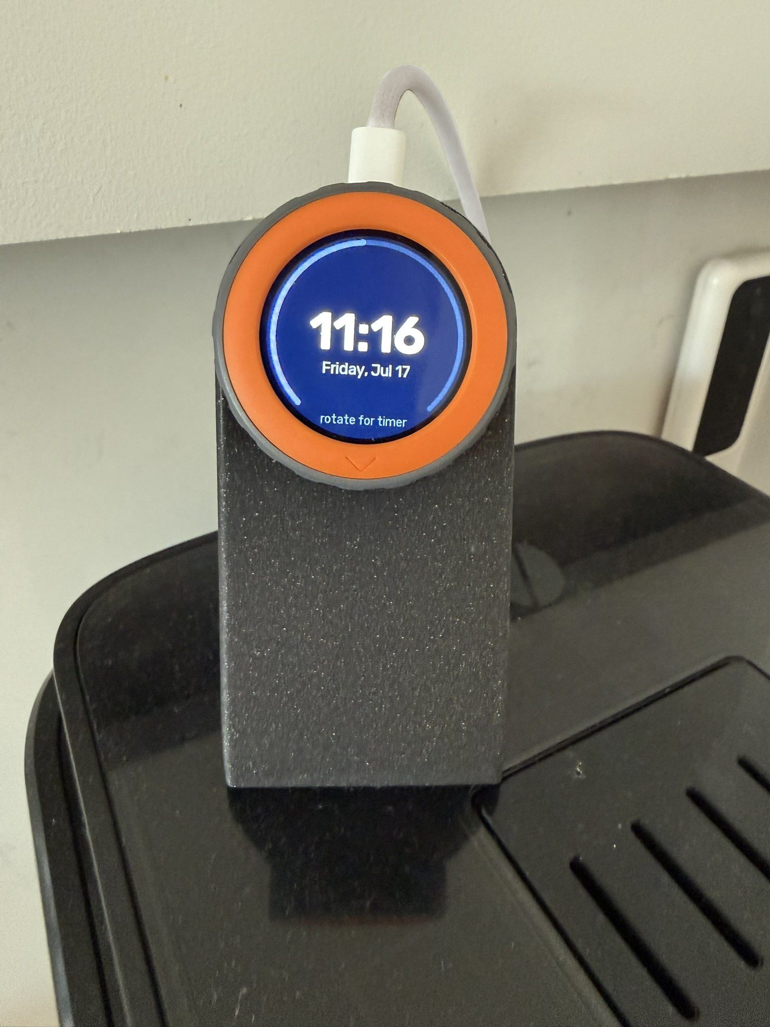
In ESPHome: define GPIO9 as a monochromatic light with restore_mode: ALWAYS_ON, set invert_colors: true on the display, and rotation: 180 in the lvgl: block. Our kitchen timer tutorial shows all three wired up.
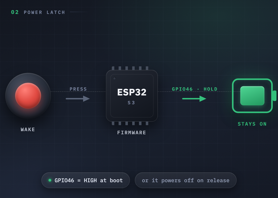
One pin, two jobs, pick one. As an input, GPIO46 senses the side (wake) button - fine for USB or DC-powered builds. On battery, the button only supplies power while physically held: firmware must drive GPIO46 HIGH early at boot or the Dial powers back down the moment it is released, so the pin cannot be your button anymore. Wall-powered: a binary_sensor on GPIO46 (inverted) gives you an extra button. Battery:…
One pin, two jobs, pick one. As an input, GPIO46 senses the side (wake) button - fine for USB or DC-powered builds. On battery, the button only supplies power while physically held: firmware must drive GPIO46 HIGH early at boot or the Dial powers back down the moment it is released, so the pin cannot be your button anymore.
Wall-powered: a binary_sensor on GPIO46 (inverted) gives you an extra button. Battery: a GPIO46 switch with restore_mode: ALWAYS_ON latches power instead.
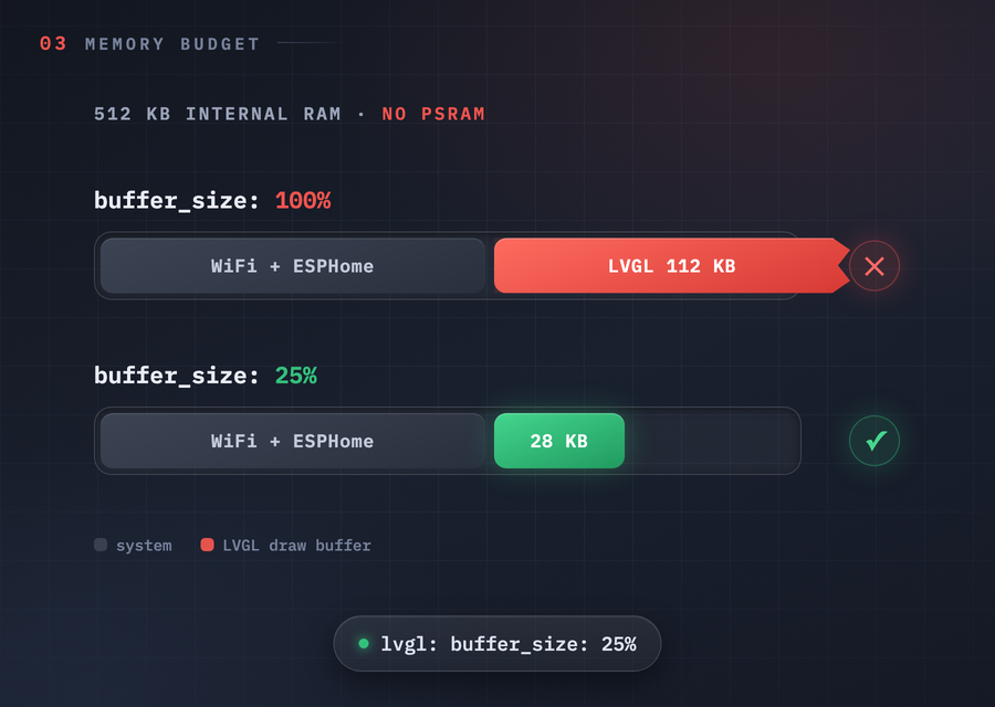
The Stamp-S3A module has 8MB flash but no PSRAM. A full-frame LVGL draw buffer for the 240x240 panel wants about 112KB of the same internal RAM WiFi lives in, so ESPHome warns at build time ("buffer_size: may need to be reduced without PSRAM") and LVGL falls back to a smaller strip buffer on its own. Typical LVGL UIs run fine with the automatic fallback. If you push the UI harder and see render trouble or…
The Stamp-S3A module has 8MB flash but no PSRAM. A full-frame LVGL draw buffer for the 240x240 panel wants about 112KB of the same internal RAM WiFi lives in, so ESPHome warns at build time ("buffer_size: may need to be reduced without PSRAM") and LVGL falls back to a smaller strip buffer on its own.
Typical LVGL UIs run fine with the automatic fallback. If you push the UI harder and see render trouble or allocation failures, pin buffer_size: 25% (working configs use 12-25%) in the lvgl: block.
Gallery
8 photos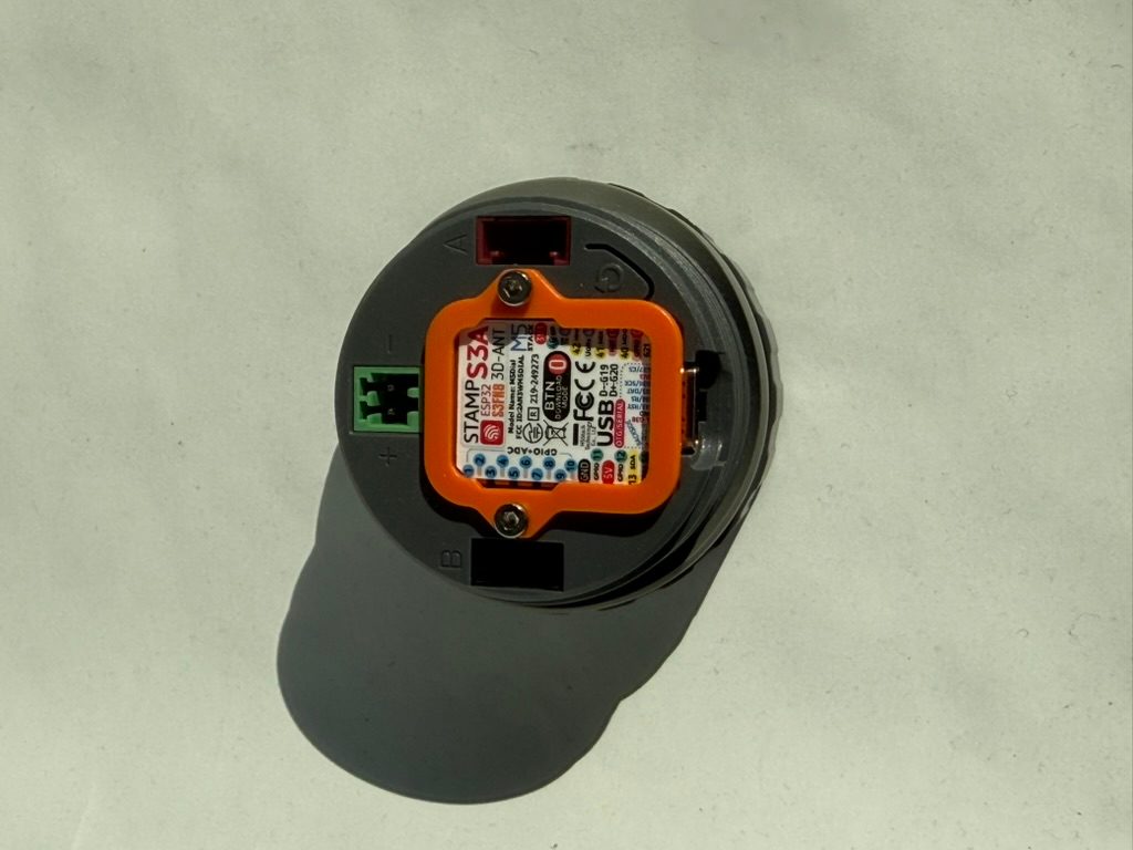
Specifications
ESP32-S3 · 51 × 51 mm · vs other ESP32 chips →Dimensions
About this board
Inside sits the ESP32-S3 - a dual-core Xtensa with vector extensions suited to AI workloads.
At $35.00 it's on the expensive side for an ESP32-S3 board - most land around $29.
Only 17 GPIO are broken out, where most ESP32-S3 boards manage about 23 - worth checking the pinout covers what you need.
Around the module: a Round TFT 1.28" 240x240 display with touch, a Grove connector, a BM8563 RTC, a buzzer, an NFC/RFID reader (WS1850S), a rotary encoder, battery charging via 1.25mm-2P and Button/Reset/Wake buttons.
It flashes over native USB - no serial-converter driver needed, which isn't a given among ESP32-S3 boards.
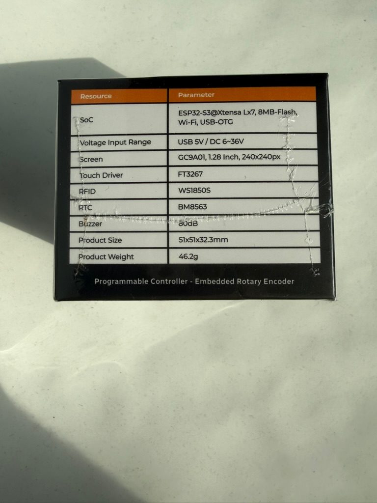
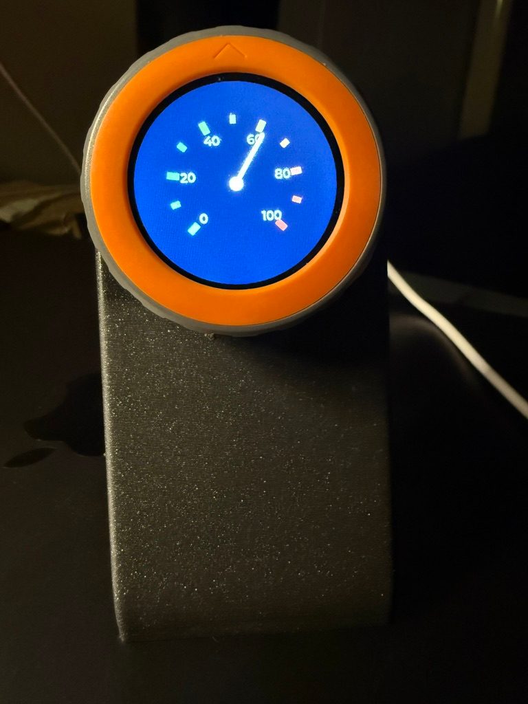
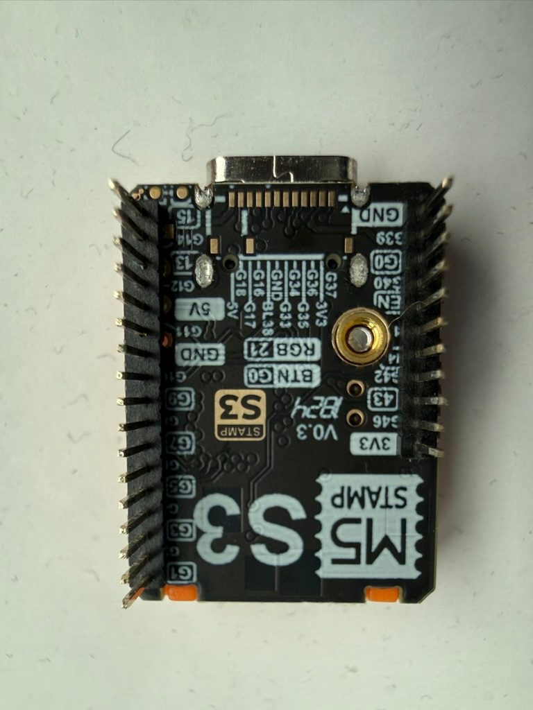
The M5Stack Dial V1.1 is a smart rotary knob built around the M5Stamp-S3A module (ESP32-S3FN8, dual-core @ 240 MHz, 8 MB flash). A 1.28" round capacitive touchscreen (GC9A01, 240x240) sits inside a physical rotary encoder, so you can turn it, tap it, or press it. The default firmware shows this off nicely: turning the dial scrolls a menu detent by detent, with a click from the buzzer at each step.
Beyond the dial there's a WS1850S RFID reader (13.56 MHz, ISO 14443 Type A/B), a BM8563 RTC, an 80dB buzzer, a physical button and two Grove ports for I2C and GPIO expansion. There's no microphone or speaker - audio feedback is buzzer-only.
Power input suits wall or panel installs: DC 6-36V via the included screw terminal, plus a 1.25mm-2P battery connector with a charging circuit for standalone use.
Compared to the original V1.0, the V1.1 swaps the controller for the Stamp-S3A, improves the antenna design and makes the physical buttons bigger.
- 1.28" round capacitive touchscreen (240x240, GC9A01 driver, FT3267 touch)
- Physical rotary encoder: 16 positions, 64 pulses per revolution
- WS1850S RFID reader - 13.56 MHz, ISO/IEC 14443 Type A/B
- BM8563 RTC with sleep-timer wake-up
- 80dB buzzer for audible feedback (no microphone or speaker)
- Wide DC 6-36V power input via included screw terminal
- 1.25mm-2P battery connector with built-in charging circuit
- Two Grove ports: Port A (I2C) and Port B (GPIO)
- Low sleep current: ~6uA on battery
- V1.1 upgrades: Stamp-S3A controller, improved antenna, larger buttons
FAQ
7 common questionsWhat is the difference between the M5Stack Dial V1.0 and V1.1?›
Does the M5Stack Dial work with ESPHome?›
Which ESPHome components drive the Dial's touch, RTC and RFID?›
ft5x06 platform (address 0x38), the BM8563 RTC uses pcf8563 (0x51), and the WS1850S RFID reader uses rc522_i2c (0x28). All three are compatible parts, but searching the ESPHome docs for the chip names finds nothing. For the display, prefer mipi_spi (model GC9A01A) - the older ili9xxx driver still works but is deprecated.How many counts does one encoder detent produce in ESPHome?›
rotary_encoder resolution: the encoder has 16 detents and 64 pulses per revolution, four quadrature edges per detent. Configs that set resolution: 4 - including M5Stack's own Home Assistant guide - get four counts per detent, which suits fine menu scrolling but breaks one-detent-one-step controls. Plain pin_a: GPIO40 / pin_b: GPIO41 works; no pullup configuration is needed.Does the M5Stack Dial have a battery?›
Does the M5Stack Dial have a speaker or microphone?›
What can I use the M5Stack Dial for?›
Where to buy
prices are typical street pricesResources
Similar boards

