
Waveshare ESP32-S3 ePaper 1.54G
Cased ESP32-S3 AIoT board with a 1.54" 4-color e-paper display, mic and speaker, SHTC3 sensor, RTC, microSD slot, and Li-ion battery management.

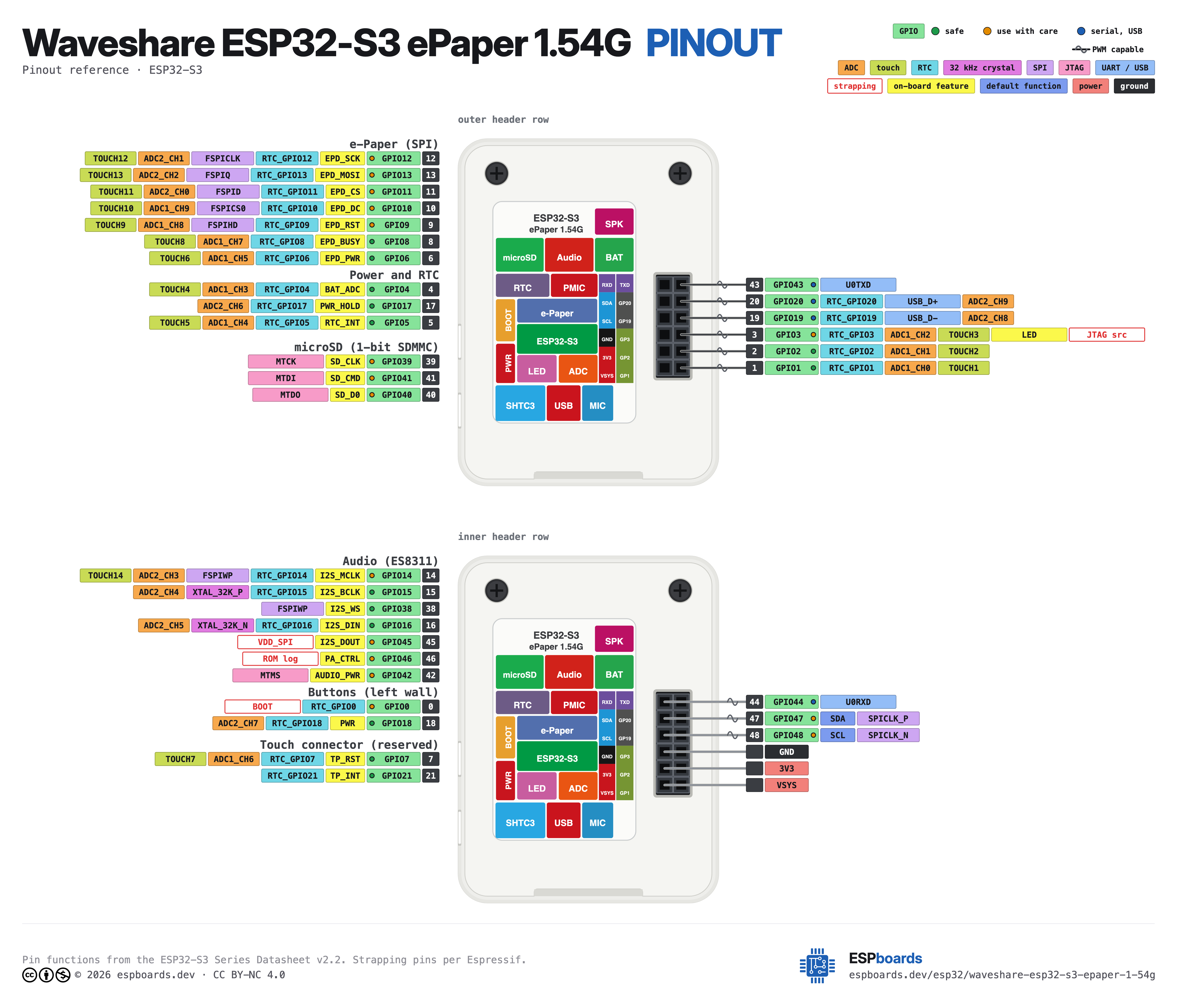
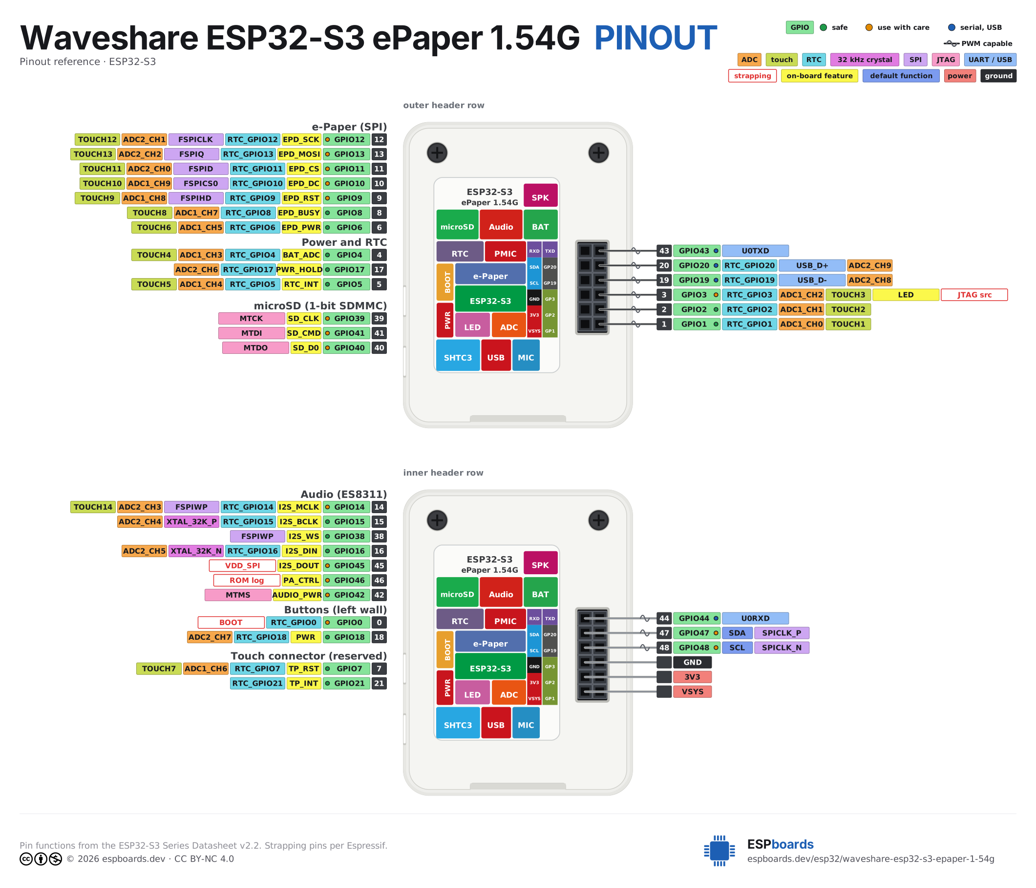
Waveshare ESP32-S3 ePaper 1.54G Pinout
12 pins · 2.54 mm pitch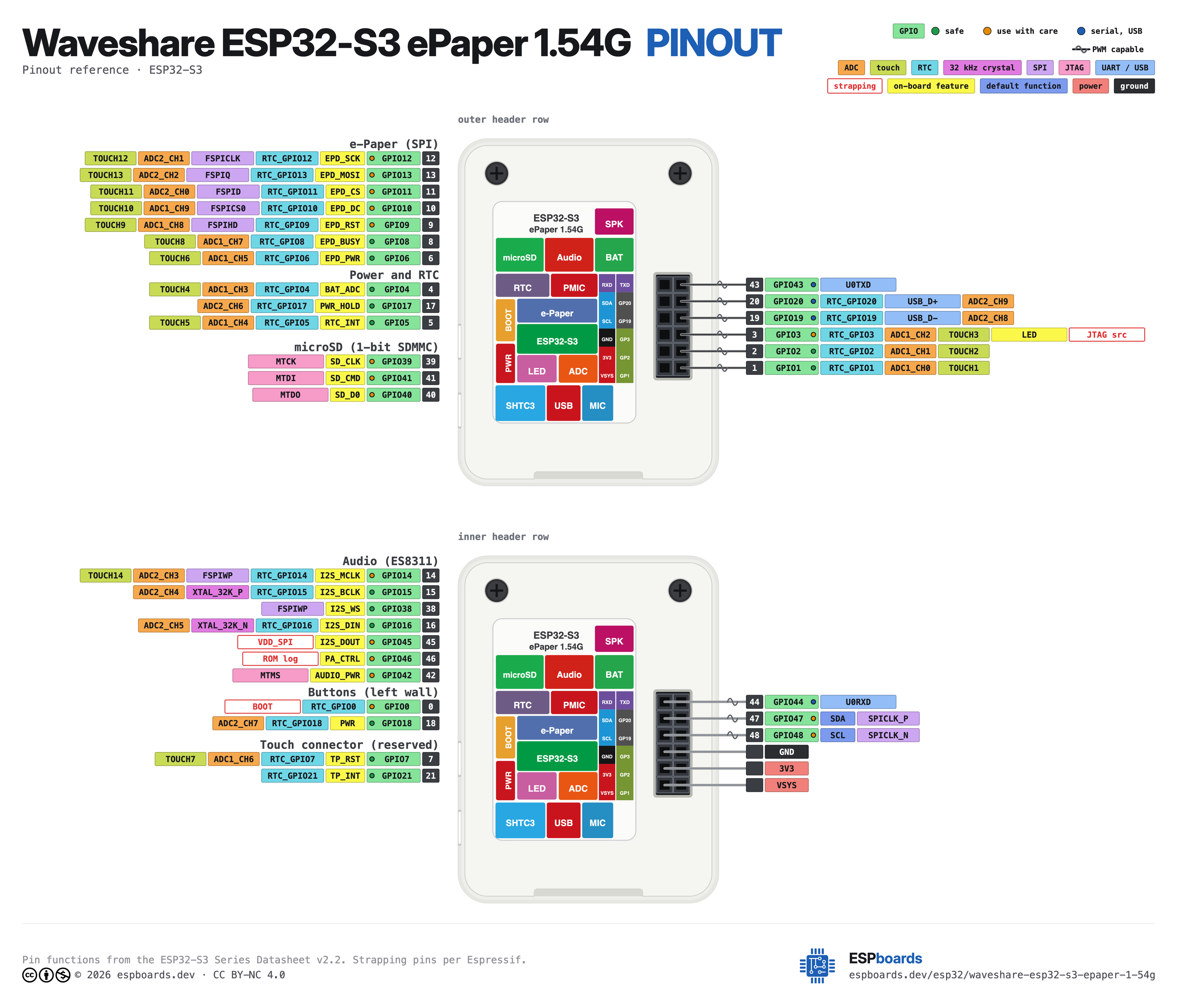
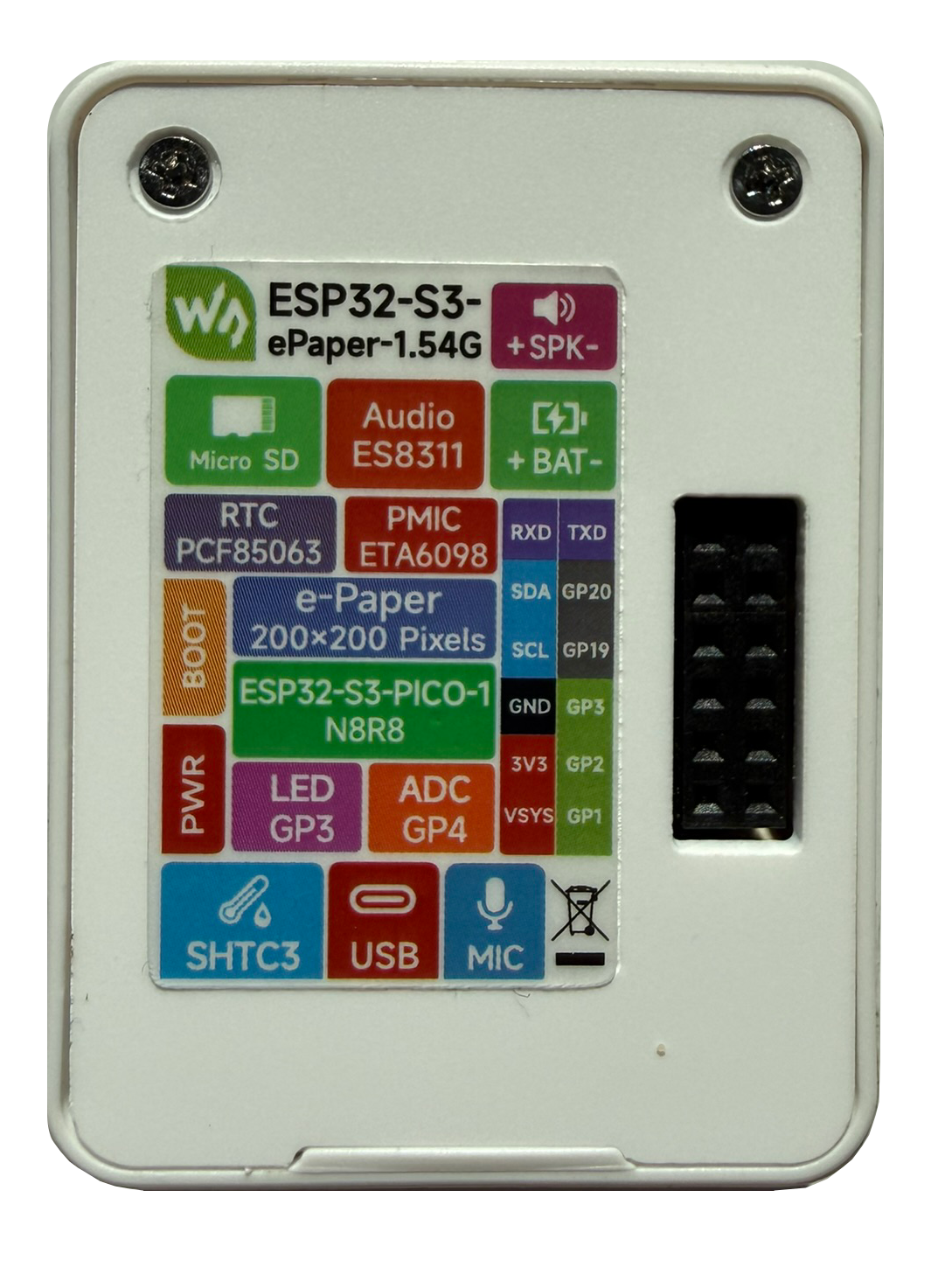
| Pin | GPIO | Labels | Status | Capabilities | Notes |
|---|---|---|---|---|---|
| 1 | 44 | RXD | uart | uart | UART0 RX |
| 2 | 47 | SDA | strapping | i2c | Shared I2C bus with RTC, SHTC3 and ES8311 |
| 3 | 48 | SCL | strapping | i2c | Shared I2C bus with RTC, SHTC3 and ES8311 |
| 4 | - | GND | ground | - | |
| 5 | - | 3V3 | power | - | 3.3V output from onboard MP1605 buck |
| 6 | - | VSYS | power | - | System supply rail (USB 5V or battery) |
| 7 | 43 | TXD | uart | uart | UART0 TX |
| 8 | 20 | GP20USB_D+ | uart | adc | Native USB D+ |
| 9 | 19 | GP19USB_D- | uart | adc | Native USB D- |
| 10 | 3 | GP3 | strapping | adc · touch | Also drives the green user LED (active low) |
| 11 | 2 | GP2 | safe | adc · touch | |
| 12 | 1 | GP1 | safe | adc · touch |
Start with these
2 pins with no boot or system involvementFreely assignable - no strapping, flash, USB or JTAG duties. Ideal first picks for buttons, sensors and LEDs.
Fine - with a little care
5 pins · 4 things to knowRXDGPIO44 UART0 receive pin (U0RXD), default serial console RX UART
Used for bootloader input (download mode via serial). If repurposed, you cannot use the default UART0 download mode for programming the chip.
SDAGPIO47SCLGPIO48 Octal SPI differential clock legs (SPICLK_P/N_DIFF), used only by the 1.8 V octal flash/PSRAM variants Other
Only the 1.8 V octal parts (ESP32-S3R8V, ESP32-S3R16V) run the differential memory clock here, and on those the pin works at 1.8 V instead of 3.3 V. On the common 3.3 V modules it is a normal GPIO - several devkits drive their RGB LED from GPIO48.
- SDAOctal SPI differential clock positive leg (SPICLK_P_DIFF), used only by the 1.8 V octal flash/PSRAM variants
- SCLOctal SPI differential clock negative leg (SPICLK_N_DIFF), used only by the 1.8 V octal flash/PSRAM variants
TXDGPIO43 UART0 transmit pin (U0TXD), default serial console TX UART
Used for bootloader output and UART console logs. If repurposed, you will lose the default serial output (and programming via UART0).
GP3 Bootstrapping pin (controls JTAG signal source) Strapping
Sampled at reset to select JTAG interface (USB Serial/JTAG controller vs. external pins). Improper use can disable external JTAG or alter debug interface.
Only if you know the tricks
2 pins · 1 thing to knowGP20GP19 USB OTG differential data pair (D- and D+) USB
By default connected to the on-chip USB Serial/JTAG controller. Using it as general GPIO without reconfiguring IO MUX will interfere with USB functionality.
- GP20USB OTG positive differential data line (USB_D+)
- GP19USB OTG negative differential data line (USB_D-)
Across 12 pins (2.54 mm pitch), the Waveshare ESP32-S3 ePaper 1.54G exposes 9 GPIO plus GND, 3V3 and VSYS for power.
For peripherals, I²C is mapped to SDA on GPIO47 and SCL on GPIO48.
On the analog side there are 5 ADC-capable pins for sensors and battery monitoring and 3 capacitive-touch inputs.
If you want zero surprises, GP2 and GP1 are free of any such role - the safest first picks. 5 of the exposed pins carry boot-time or system duties on the ESP32-S3 (RXD, SDA, SCL and 2 more).
Guides & tutorials

Getting started
flash your first firmware in ~2 minutesBoard: ESP32S3 Dev Module USB CDC On Boot: Enabled Flash Size: 8MB (64Mb) Flash Mode: QIO PSRAM: OPI PSRAM Partition Scheme: 8M with spiffs (3MB APP/1.5MB SPIFFS) Upload Speed: 921600
// toggle GPIO2 - wire an LED and resistor to it
void setup() {
  pinMode(2, OUTPUT);
}
void loop() {
  digitalWrite(2, HIGH); delay(500);
  digitalWrite(2, LOW);  delay(500);
}[env:waveshare-esp32-s3-epaper-1-54g]
platform = espressif32
board = esp32-s3-devkitc-1
framework = arduino
monitor_speed = 115200
upload_speed = 921600
board_build.arduino.memory_type = qio_opi
build_flags = -DBOARD_HAS_PSRAMesp32-s3-devkitc-1 - or type it after board =.esp32:
board: esp32-s3-devkitc-1
variant: esp32s3
framework:
type: esp-idf
psram:
mode: octal
speed: 80MHz
# blink - GPIO2
output:
- platform: gpio
pin: 2
id: led_out
light:
- platform: binary
name: "LED"
output: led_outesp32-s3-devkitc-1 (same ids as PlatformIO).esptool.py --chip esp32s3 --port /dev/ttyACM0 \
--baud 921600 write_flash 0x0 firmware.bin--port = your /dev/tty* (macOS/Linux) or COMx (Windows).Good to know
board-specific quirks worth 60 secondsOnly GPIO1 and GPIO2 on the header are free to use. GPIO3 also lights the green LED, GPIO19/20 are the native USB lines, GPIO43/44 are UART0, and GPIO47/48 are the shared I2C bus (add I2C devices there instead of using the pins as GPIO). Everything else on the S3 is wired to something on the board, listed below, so check it before you reuse a pin in your firmware. e-paper panel (SPI): SCK GPIO12, MOSI GPIO13, CS…
Only GPIO1 and GPIO2 on the header are free to use. GPIO3 also lights the green LED, GPIO19/20 are the native USB lines, GPIO43/44 are UART0, and GPIO47/48 are the shared I2C bus (add I2C devices there instead of using the pins as GPIO). Everything else on the S3 is wired to something on the board, listed below, so check it before you reuse a pin in your firmware.
- e-paper panel (SPI): SCK GPIO12, MOSI GPIO13, CS GPIO11, DC GPIO10, RST GPIO9, BUSY GPIO8 (inverted), panel power GPIO6 (LOW = on)
- Touch connector (reserved): RST GPIO7, INT GPIO21, I2C on GPIO47/48
- Audio (ES8311 + NS4150B): I2S MCLK GPIO14, BCLK GPIO15, WS GPIO38, codec to ESP (DIN) GPIO16, ESP to codec (DOUT) GPIO45, amplifier enable GPIO46, audio power GPIO42 (LOW = on)
- microSD (1-bit SDMMC): CLK GPIO39, CMD GPIO41, D0 GPIO40
- I2C bus: SDA GPIO47, SCL GPIO48 - PCF85063 RTC, SHTC3, ES8311 and the touch connector. RTC interrupt on GPIO5
- Power and buttons: battery ADC GPIO4 (1/2 divider), power latch hold GPIO17 (HIGH = stay on), PWR button GPIO18, BOOT button GPIO0
- Not usable: GPIO33-37 belong to the in-package octal PSRAM of the PICO-1-N8R8
Source: the GPIO allocation table in Waveshare's schematic, cross-checked against the pin definitions in their ESP-IDF demos.
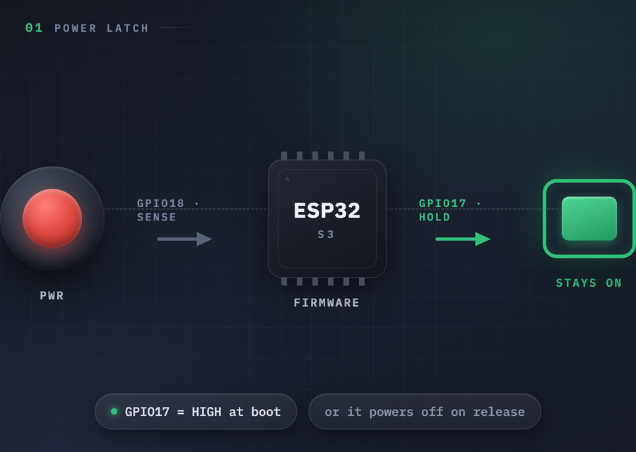
On battery there is no hardware power switch: the PWR button is sensed on GPIO18 and power is held by GPIO17. Your firmware must drive GPIO17 HIGH early at boot, otherwise the board switches off the moment the button is released. A long press is whatever your firmware decides it is. In ESPHome, set a GPIO17 output to ON in on_boot at priority 600, and use gpio_hold_en() before deep sleep so the latch survives…
On battery there is no hardware power switch: the PWR button is sensed on GPIO18 and power is held by GPIO17. Your firmware must drive GPIO17 HIGH early at boot, otherwise the board switches off the moment the button is released. A long press is whatever your firmware decides it is.
In ESPHome, set a GPIO17 output to ON in on_boot at priority 600, and use gpio_hold_en() before deep sleep so the latch survives it. Our climate display tutorial has the full pattern.
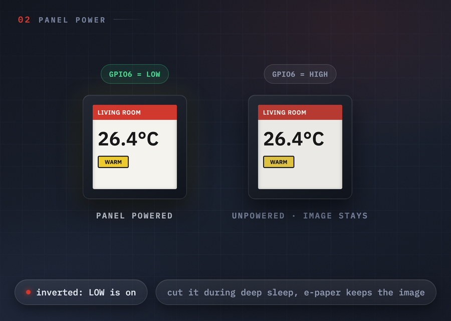
GPIO6 LOW powers the e-paper panel, HIGH cuts it. Cut panel power during deep sleep: the image persists with the panel unpowered, which is exactly what e-paper is for. Miss the inversion and you get a blank display and no error anywhere.
The busy pin (GPIO8) is also inverted on this panel: idle is HIGH, busy is LOW.
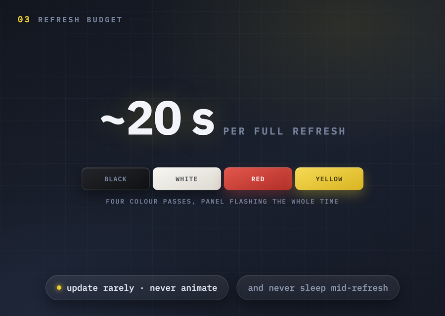
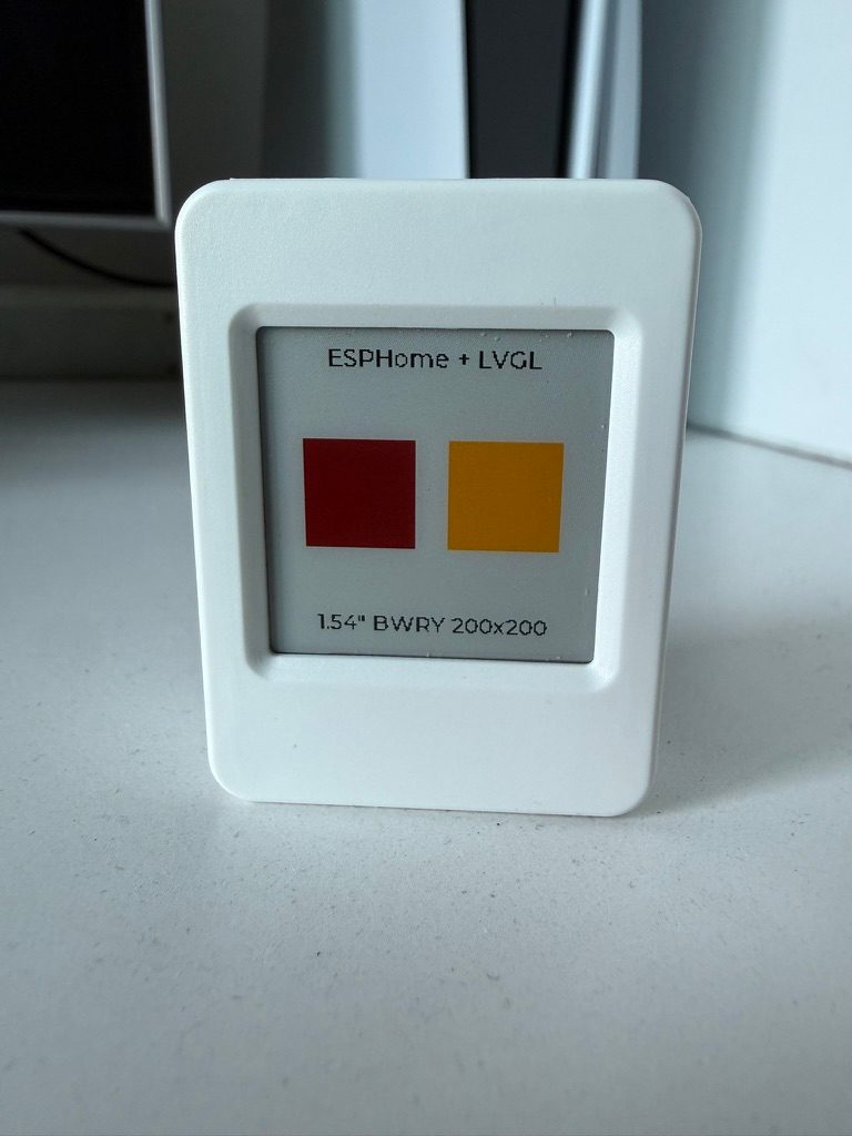
The 4-color BWRY panel needs roughly 20 s for a full refresh (fast refresh about 15 s), flashing through its color cycle the whole time. Design for it: update rarely, never animate, and do not enter deep sleep mid-refresh or the panel is left in a half-drawn state. In ESPHome/LVGL set update_interval: never on the display, update_when_display_idle: false, animated: false on bars, and wait ~30 s after…
The 4-color BWRY panel needs roughly 20 s for a full refresh (fast refresh about 15 s), flashing through its color cycle the whole time. Design for it: update rarely, never animate, and do not enter deep sleep mid-refresh or the panel is left in a half-drawn state.
In ESPHome/LVGL set update_interval: never on the display, update_when_display_idle: false, animated: false on bars, and wait ~30 s after triggering a refresh before sleeping.
Gallery
6 photos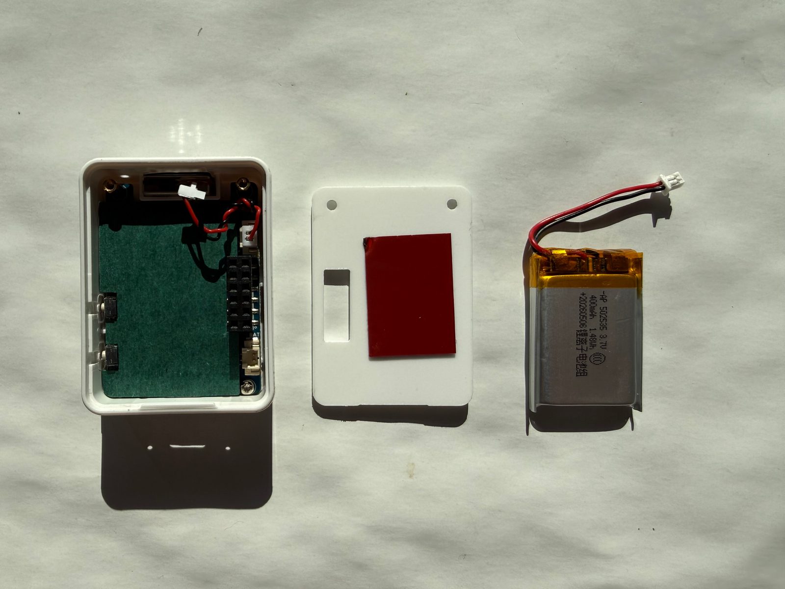
Downloads
Free for non-commercial use, credit espboards.dev · License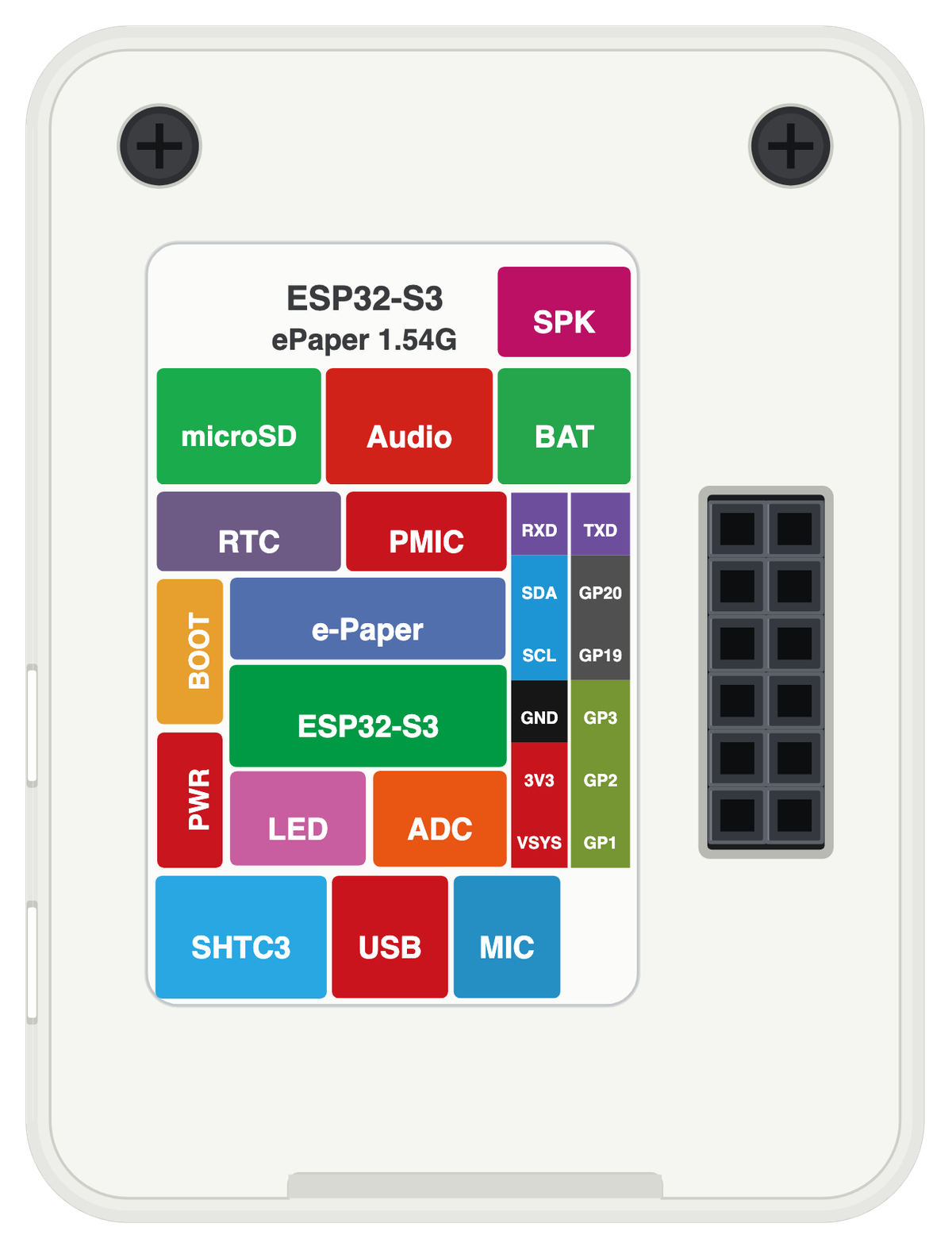
Board illustration
The bare Waveshare ESP32-S3 ePaper 1.54G board drawn to scale at 53 × 39.8 mm, with no pin labels on it. Made for slide decks, wiring diagrams and project write-ups where a photo is too busy. Take the scalable SVG for print or editing, the high-resolution PNG to drop straight in, or the transparent PNG when you need it with no background behind it.
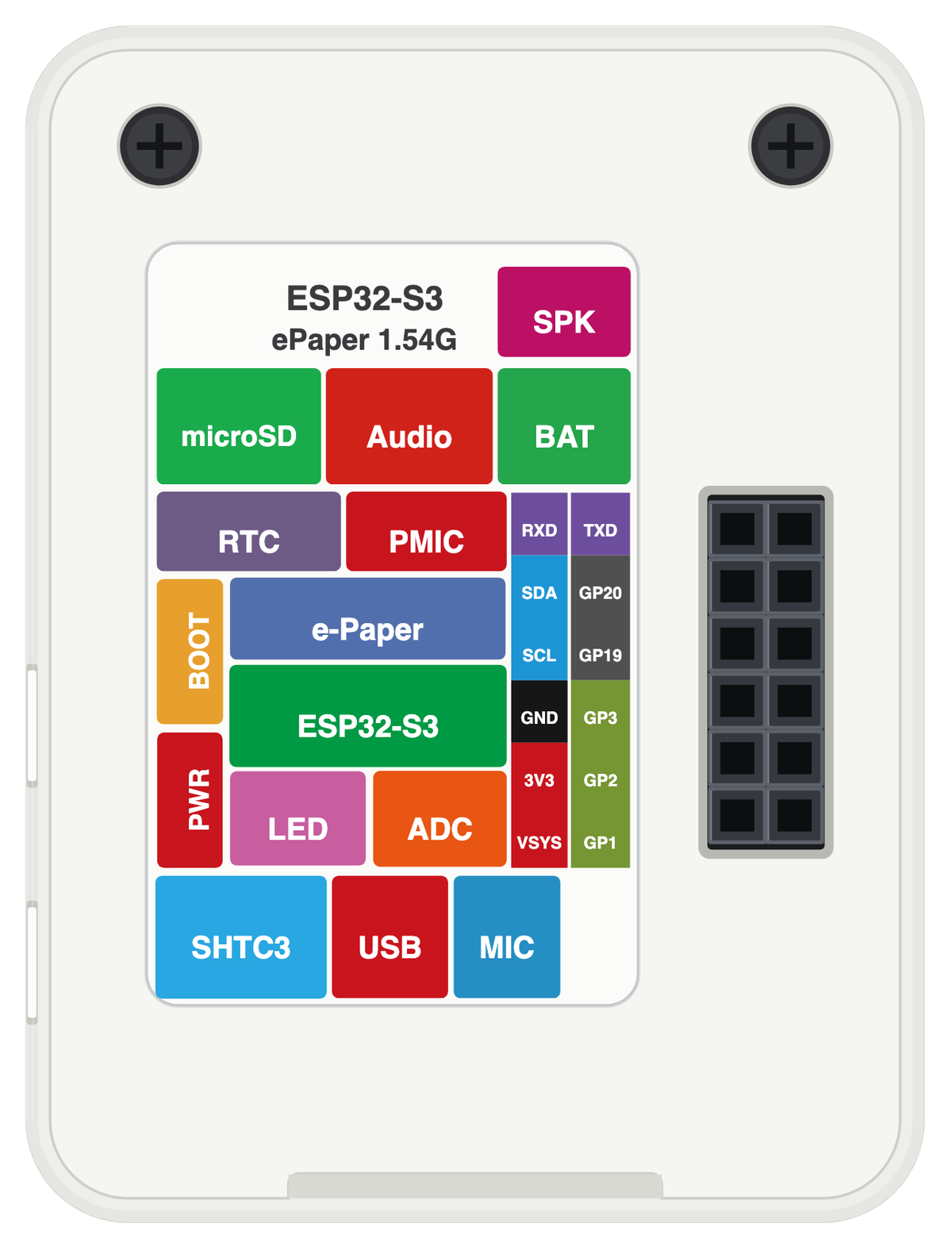
Pinout diagram
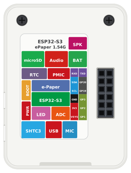
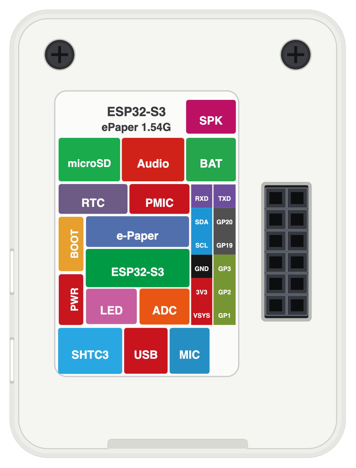
Every pin on both sides of the board with its functions, drawn by ESPboards from the ESP32-S3 Series Datasheet v2.2 - the same sheet shown at the top of this page. The PNG is a high-resolution image for screens, the SVG is vector so it stays sharp at any size, and the PDF is laid out to print on A4 or Letter.
Yours to use, share and adapt for non-commercial work, as long as you credit espboards.dev - the full terms and ready-made credit lines are here.
Specifications
ESP32-S3 · 53 × 39.8 mm · vs other ESP32 chips →Dimensions

About this board
At its core is the ESP32-S3 - a dual-core Xtensa with vector extensions suited to AI workloads.
Expect to pay about $17.99 - less than the ~$29 most ESP32-S3 boards go for.
Only 9 GPIO are broken out, where most ESP32-S3 boards manage about 23 - worth checking the pinout covers what you need.
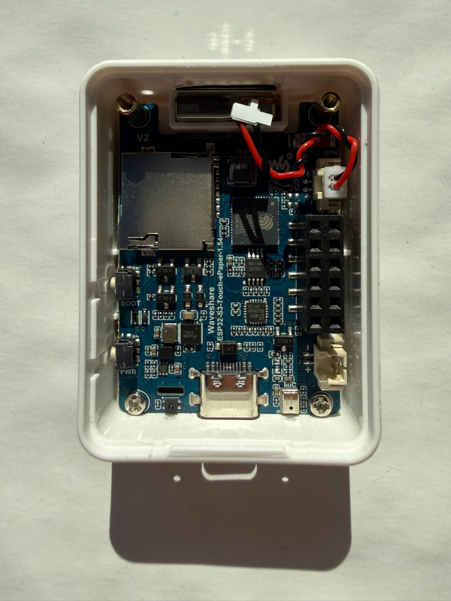
Onboard you'll find 8MB (OPI) PSRAM, an ePaper 1.54" 200x200 display, a microSD slot, a microphone, a speaker, a speaker connector (MX1.25 2PIN), an audio codec (ES8311), an amplifier (NS4150B), a PCF85063 RTC, an environmental sensor (SHTC3), battery charging (ETA6098) via GH1.25 2PIN, status LEDs (Charge, User (GPIO3)) and Boot/Power buttons.
It flashes over native USB - no serial-converter driver needed, which isn't a given among ESP32-S3 boards.
- 4-color e-paper panel: red / yellow / black / white
- Full refresh ~20 s, fast refresh ~15 s
- ESP32-S3-PICO-1-N8R8 SiP - 8MB flash + 8MB PSRAM in-package
- Battery voltage sensing on GPIO4 (ADC, 1/2 divider)
- PWR button is a firmware-controlled power latch (GPIO18 sense, GPIO17 hold/cut)
- Touch-panel FPC connector reserved on this variant (GPIO7 reset, GPIO21 interrupt)
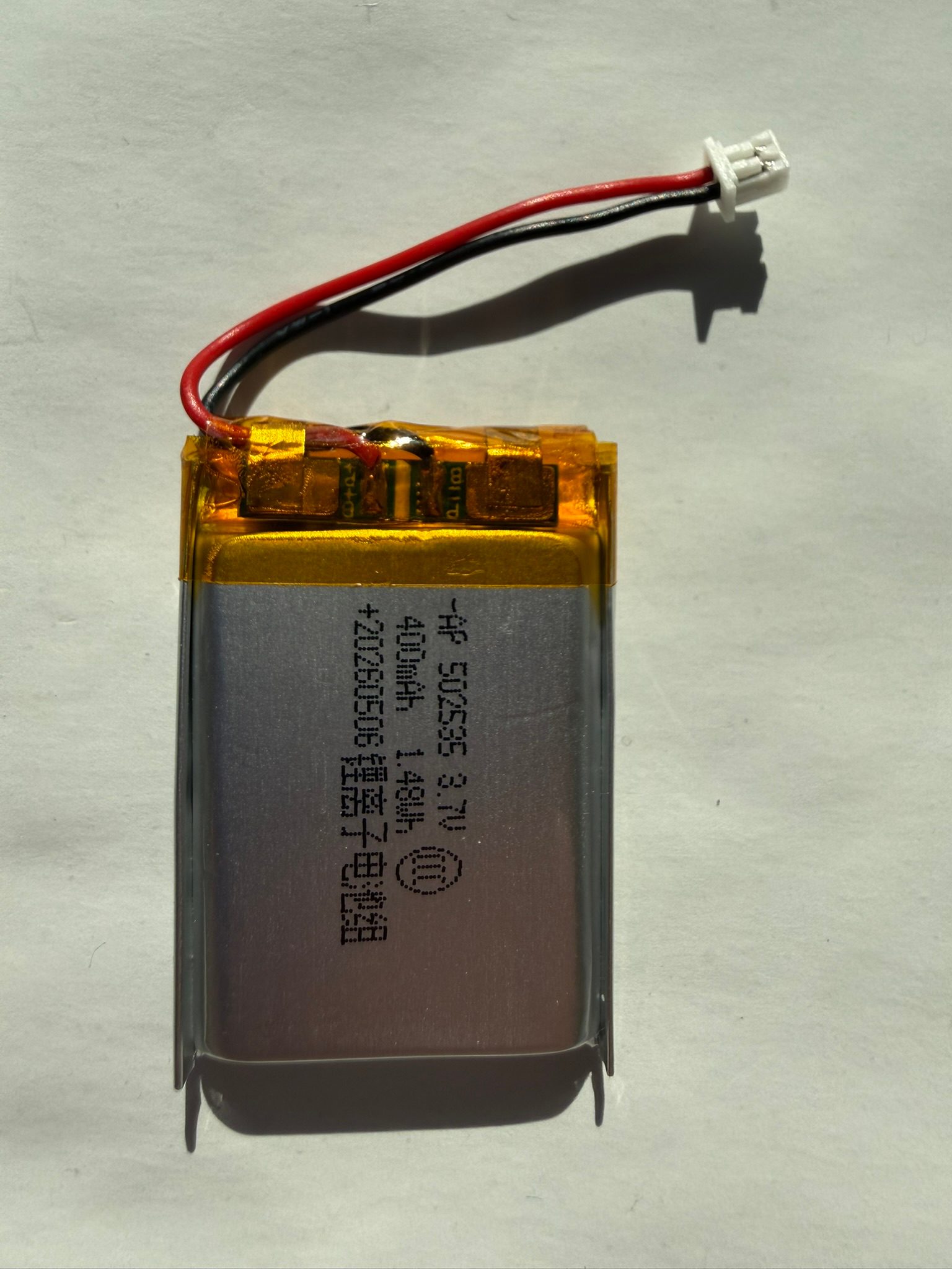
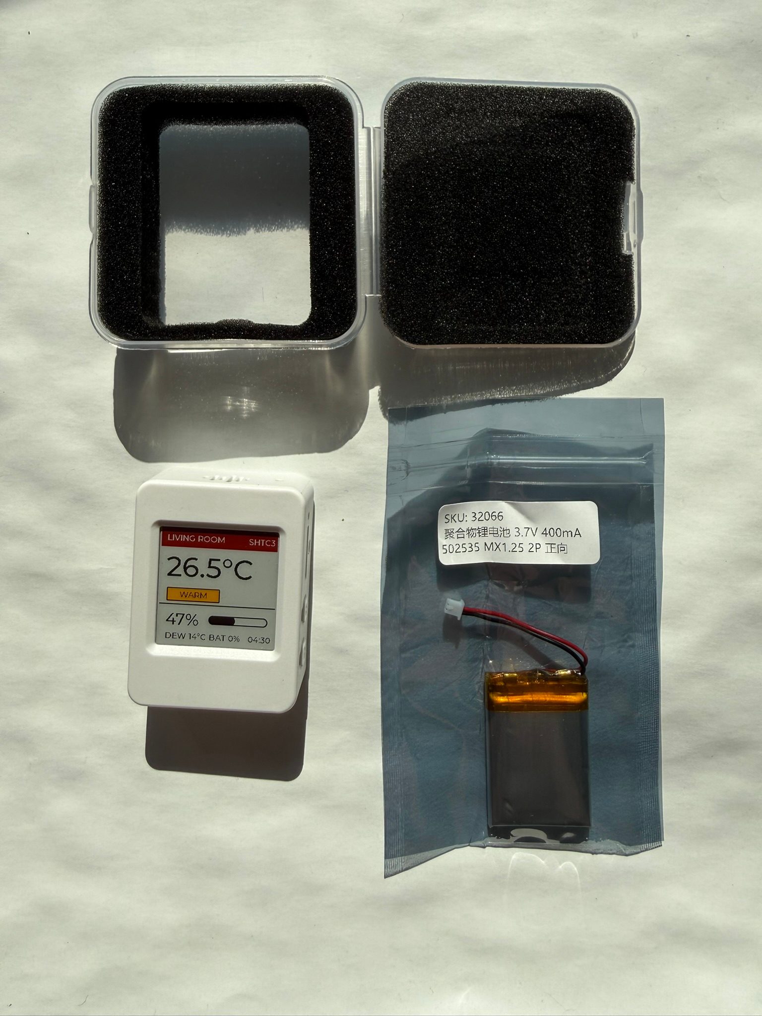
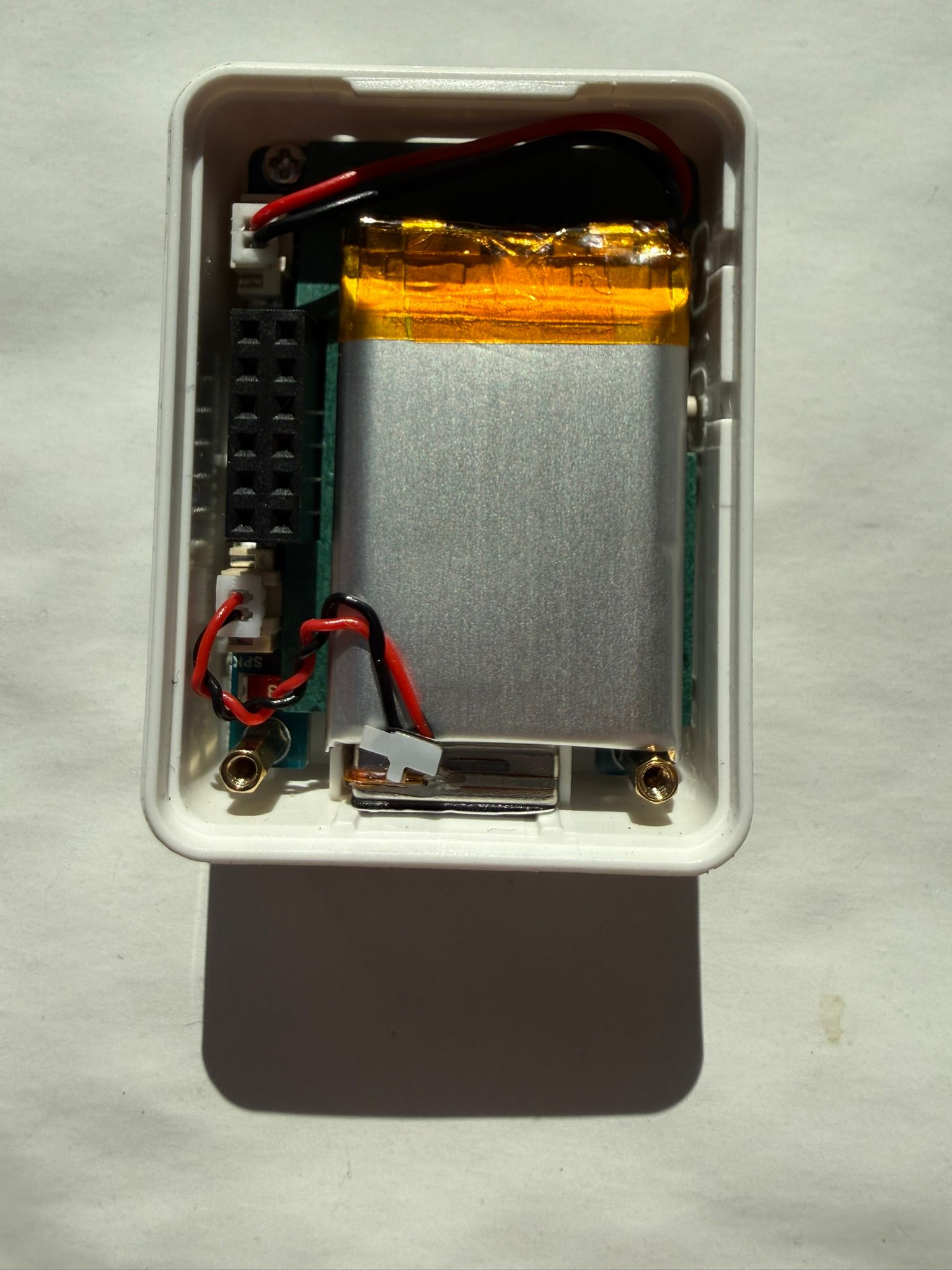
- Ships assembled in a snap-fit case; battery SKU includes a 3.7V Li-ion cell
FAQ
5 common questionsWhy does the display take up to 20 seconds to refresh?›
How do I switch the board on when it runs from the battery?›
Does the Waveshare ESP32-S3-ePaper-1.54G work with ESPHome?›
How long does it run on battery?›
Can I use the GPIO pins for my own sensors?›
Where to buy
prices are typical street pricesResources
Similar boards

