
XIAO ESP32C5
Thumb-sized ESP32-C5 board by Seeed Studio with dual-band 2.4/5 GHz Wi-Fi 6, BLE 5, 8 MB PSRAM, USB-C and LiPo charging.

XIAO ESP32C5 Pinout
14 pins · 2.54 mm pitch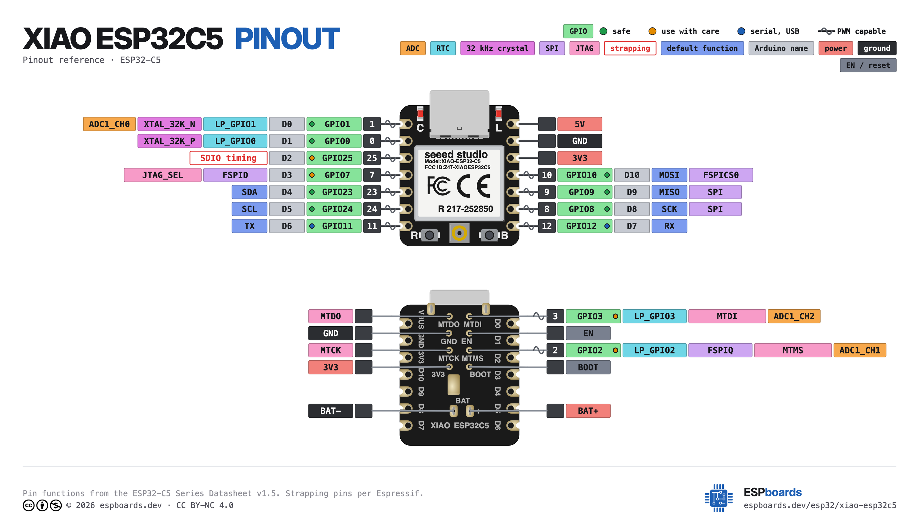
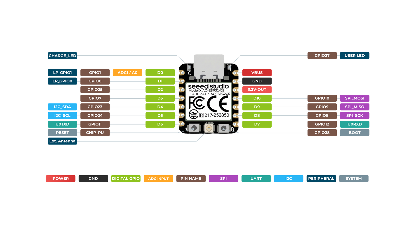
| Pin | GPIO | Labels | Status | Capabilities | Notes |
|---|---|---|---|---|---|
| 1 | 1 | D0A0GPIO1LP_GPIO1 | safe | adc · pwm | |
| 2 | 0 | D1GPIO0LP_GPIO0 | safe | pwm | |
| 3 | 25 | D2GPIO25 | strapping | pwm | |
| 4 | 7 | D3GPIO7 | strapping | pwm | |
| 5 | 23 | D4SDAGPIO23 | safe | i2c · pwm | |
| 6 | 24 | D5SCLGPIO24 | safe | i2c · pwm | |
| 7 | 11 | D6TXGPIO11 | uart | uart · pwm | |
| 8 | - | 5V | power | - | 5V power input/output |
| 9 | - | GND | ground | - | |
| 10 | - | 3V3 | power | - | 3.3V output |
| 11 | 10 | D10MOSIGPIO10 | safe | spi · pwm | |
| 12 | 9 | D9MISOGPIO9 | safe | spi · pwm | |
| 13 | 8 | D8SCKGPIO8 | safe | spi · pwm | |
| 14 | 12 | D7RXGPIO12 | uart | uart · pwm |
Start with these
9 pins with no boot or system involvementFreely assignable - no strapping, flash, USB or JTAG duties. Ideal first picks for buttons, sensors and LEDs.
Fine - with a little care
2 pins · 2 things to knowD2GPIO25 Strapping pin; SDIO input-sampling / output-driving clock-edge control (with MTDI). Floating by default. Strapping
Latched at reset to set SDIO clock-edge behaviour; avoid driving at boot unless configuring SDIO timing. Free as GPIO after reset.
D3GPIO7 Strapping pin; selects the JTAG signal source during early boot. Has no internal pull resistors. JTAG
Must be driven to a defined level by external circuitry at reset (never left floating) to select the JTAG source; free as GPIO afterwards.
Across 14 pins (2.54 mm pitch), the XIAO ESP32C5 exposes 11 GPIO plus 5V, GND and 3V3 for power.
Peripheral wiring is straightforward: I²C is mapped to SDA on GPIO23 and SCL on GPIO24; the SPI bus (MOSI, MISO, SCK) is broken out in full; TX/RX on GPIO11 and GPIO12 cover serial logging and flashing.
Beyond plain digital I/O you get 1 ADC-capable pin for sensors and battery monitoring and PWM on every GPIO.
2 of the exposed pins carry boot-time or system duties on the ESP32-C5 (D2 and D3) - check the guidance above before wiring anything to them. D0, D1, D4, D5 and 5 more are free of any such role - the safest first picks.
Getting started
flash your first firmware in ~2 minutesBoard: XIAO_ESP32C5 USB CDC On Boot: Enabled Flash Size: 8MB (64Mb) Flash Mode: QIO PSRAM: QSPI PSRAM Partition Scheme: 8M with spiffs (3MB APP/1.5MB SPIFFS) Upload Speed: 921600
// blink the onboard user LED
void setup() {
  pinMode(27, OUTPUT);
}
void loop() {
  digitalWrite(27, HIGH); delay(500);
  digitalWrite(27, LOW);  delay(500);
}[env:xiao-esp32c5]
platform = https://github.com/pioarduino/platform-espressif32/releases/download/stable/platform-espressif32.zip
board = seeed_xiao_esp32c5
framework = arduino
monitor_speed = 115200
upload_speed = 921600
board_build.arduino.memory_type = qio_qspi
build_flags = -DBOARD_HAS_PSRAMseeed_xiao_esp32c5 - or type it after board =.esp32:
board: seeed_xiao_esp32c5
variant: esp32c5
framework:
type: esp-idf
psram:
mode: quad
speed: 80MHz
# blink - GPIO27
output:
- platform: gpio
pin: 27
id: led_out
light:
- platform: binary
name: "LED"
output: led_outseeed_xiao_esp32c5 (same ids as PlatformIO).esptool.py --chip esp32c5 --port /dev/ttyACM0 \
--baud 921600 write_flash 0x2000 firmware.bin--port = your /dev/tty* (macOS/Linux) or COMx (Windows).Good to know
board-specific quirks worth 60 seconds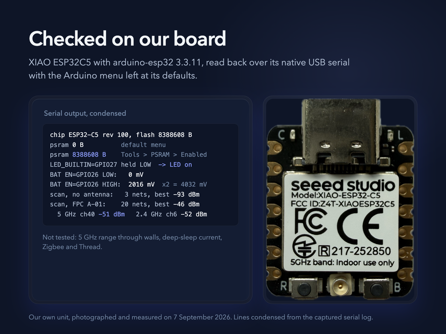
We ran a XIAO ESP32C5 on the bench with arduino-esp32 3.3.11 and read everything back over its native USB serial port. The serial monitor works with the Arduino menu left at its defaults: USB CDC On Boot ships Enabled. The user LED is GPIO27 and lights when the pin is driven LOW. Flash reports 8388608 bytes. PSRAM reports 0 bytes on the default menu and 8388608 bytes with Tools > PSRAM > Enabled. Battery sense: with…
We ran a XIAO ESP32C5 on the bench with arduino-esp32 3.3.11 and read everything back over its native USB serial port.
- The serial monitor works with the Arduino menu left at its defaults: USB CDC On Boot ships Enabled.
- The user LED is GPIO27 and lights when the pin is driven LOW.
- Flash reports 8388608 bytes. PSRAM reports 0 bytes on the default menu and 8388608 bytes with Tools > PSRAM > Enabled.
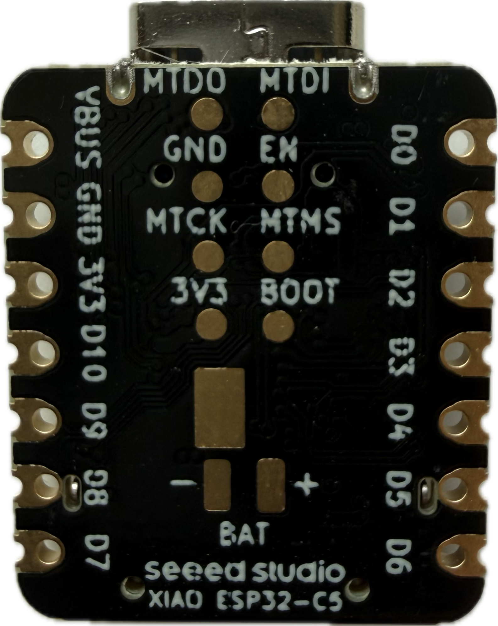
- Battery sense: with GPIO26 LOW the ADC on GPIO6 reads 0 mV; with it HIGH it reads half the BAT+ voltage.
- Without an antenna a Wi-Fi scan found 3 networks, all around -93 dBm. With the bundled FPC antenna it found 20, and our router's 5 GHz SSID came in within a few dB of its 2.4 GHz signal.
Not tested here: 5 GHz range through walls, deep-sleep current, Zigbee and Thread. Those figures come from Seeed's and Espressif's documentation.
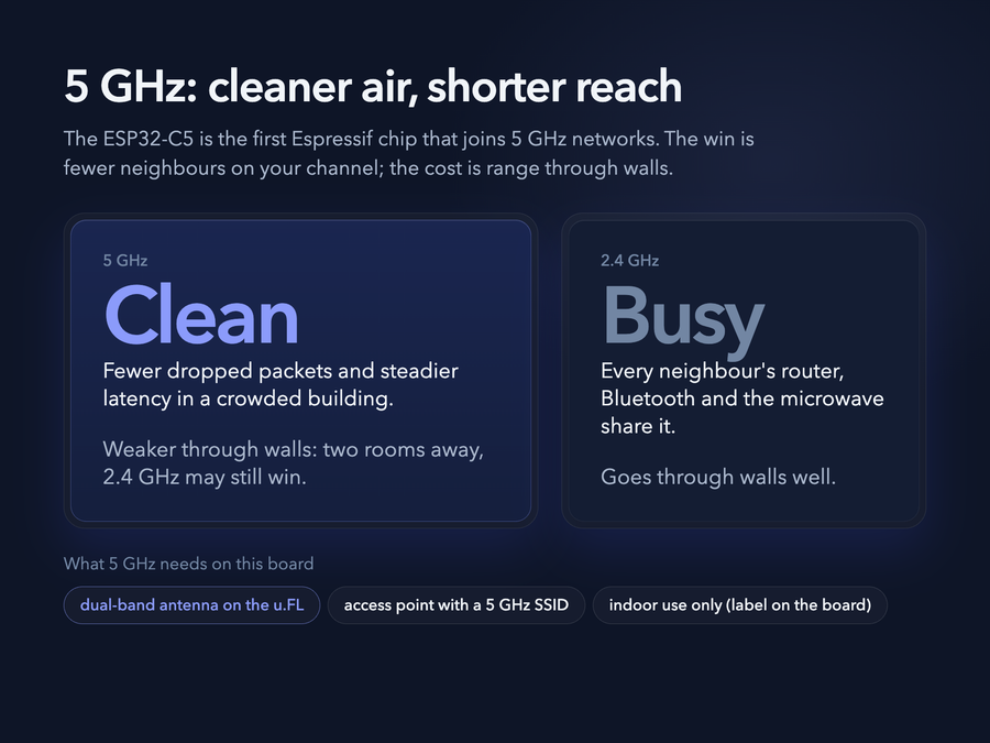
The ESP32-C5 is the first Espressif chip that can join a 5 GHz network. The practical win is not speed - it is a clean channel. In a building where every neighbour's router sits on 2.4 GHz, a 5 GHz link drops far fewer packets and keeps latency steady. The trade-off is range: 5 GHz does not pass through walls as well, so a device two rooms away may still be better off on 2.4 GHz. Two things to get right: the…
The ESP32-C5 is the first Espressif chip that can join a 5 GHz network. The practical win is not speed - it is a clean channel. In a building where every neighbour's router sits on 2.4 GHz, a 5 GHz link drops far fewer packets and keeps latency steady. The trade-off is range: 5 GHz does not pass through walls as well, so a device two rooms away may still be better off on 2.4 GHz.
Two things to get right: the external antenna you attach must be dual-band (a 2.4 GHz-only antenna will connect on 2.4 GHz and struggle on 5 GHz), and your access point must broadcast the same SSID on both bands or you pick the band by SSID. One thing to check before judging 5 GHz range: Seeed's C5 spec table lists the bundled FPC antenna as a 2.4 GHz (2.9 dBi) part, while Seeed's listing for that same antenna (FPC Antenna A-01 for XIAO ESP32C3/C5, SKU 318020748) calls it a 2.4 GHz/5 GHz combo. If 5 GHz is weak, the antenna is the first thing to swap.
In arduino-esp32 3.3 the sketch code is unchanged - WiFi.begin() picks the band - and WiFi.setBandMode() lets you pin it to 5 GHz or 2.4 GHz only.
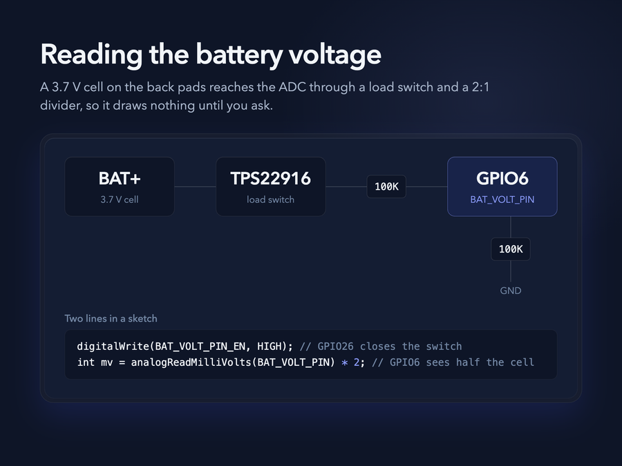
A 3.7 V lithium cell solders to the pads on the back, and the board can measure it. Seeed's wiki: the XIAO ESP32C5 carries the SGM40567 charging chip plus a TPS22916CYFPR load switch for voltage acquisition, so the divider only draws current when you ask it to. BAT_VOLT_PIN is GPIO6 - the ADC input that sees the divided cell voltage. BAT_VOLT_PIN_EN is GPIO26 - drive it HIGH to switch the measurement circuit on. The…
A 3.7 V lithium cell solders to the pads on the back, and the board can measure it. Seeed's wiki: the XIAO ESP32C5 carries the SGM40567 charging chip plus a TPS22916CYFPR load switch for voltage acquisition, so the divider only draws current when you ask it to.
- BAT_VOLT_PIN is GPIO6 - the ADC input that sees the divided cell voltage.
- BAT_VOLT_PIN_EN is GPIO26 - drive it HIGH to switch the measurement circuit on.
- The divider is two 100K resistors, so the reading is half the cell voltage - multiply by 2.
#include <Arduino.h>

void setup() {
  Serial.begin(115200);
  pinMode(BAT_VOLT_PIN, INPUT);           // ADC input
  pinMode(BAT_VOLT_PIN_EN, OUTPUT);
  digitalWrite(BAT_VOLT_PIN_EN, HIGH);    // enable the measurement circuit
}

void loop() {
  uint32_t Vbatt = 0;
  for (int i = 0; i < 16; i++) {
    Vbatt += analogReadMilliVolts(BAT_VOLT_PIN);   // read and accumulate
  }
  float Vbattf = 2 * Vbatt / 16 / 1000.0;   // 1:2 divider, mV to V
  Serial.println(Vbattf, 3);
  delay(1000);
}
analogReadMilliVolts() applies the chip's factory ADC calibration, so you skip the raw-count-to-volts maths. Seeed averages 16 samples to settle the noise; the C5's ADC range is 0~3300 mV, which is why the 1:2 divider is there.
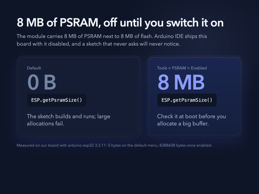
The module's 8 MB of PSRAM is disabled in arduino-esp32's default menu for this board. Set Tools → PSRAM → "Enabled" or ESP.getPsramSize() reports 0 and any large allocation fails. We measured it on a board here with arduino-esp32 3.3.11: 0 bytes on the default menu, 8388608 bytes once enabled. With PSRAM disabled the sketch still builds and runs, so check ESP.getPsramSize() at boot before you allocate a big…
The module's 8 MB of PSRAM is disabled in arduino-esp32's default menu for this board. Set Tools → PSRAM → "Enabled" or ESP.getPsramSize() reports 0 and any large allocation fails. We measured it on a board here with arduino-esp32 3.3.11: 0 bytes on the default menu, 8388608 bytes once enabled.
With PSRAM disabled the sketch still builds and runs, so check ESP.getPsramSize() at boot before you allocate a big buffer.
Gallery
4 photos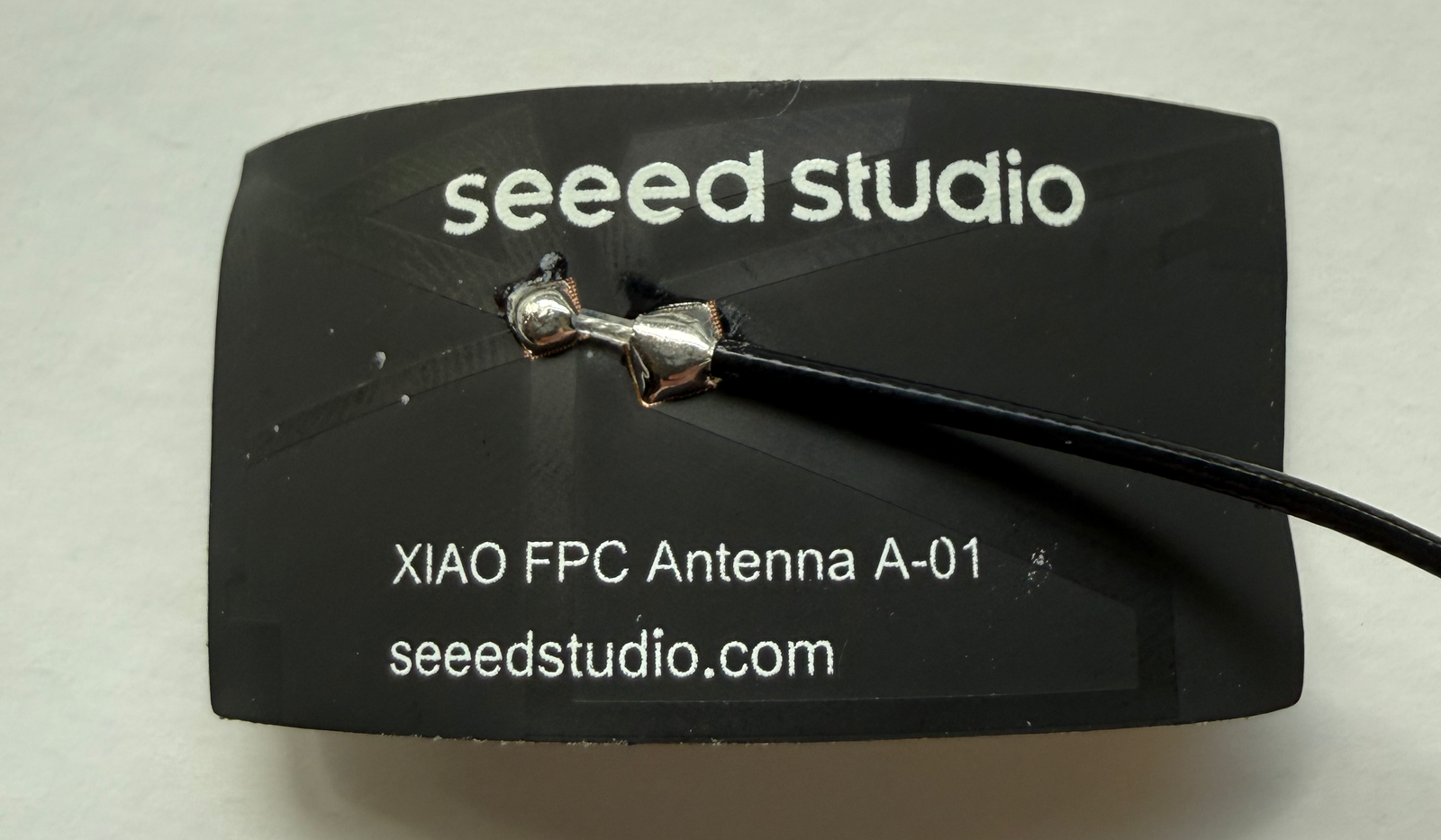
Downloads
Free for non-commercial use, credit espboards.dev · License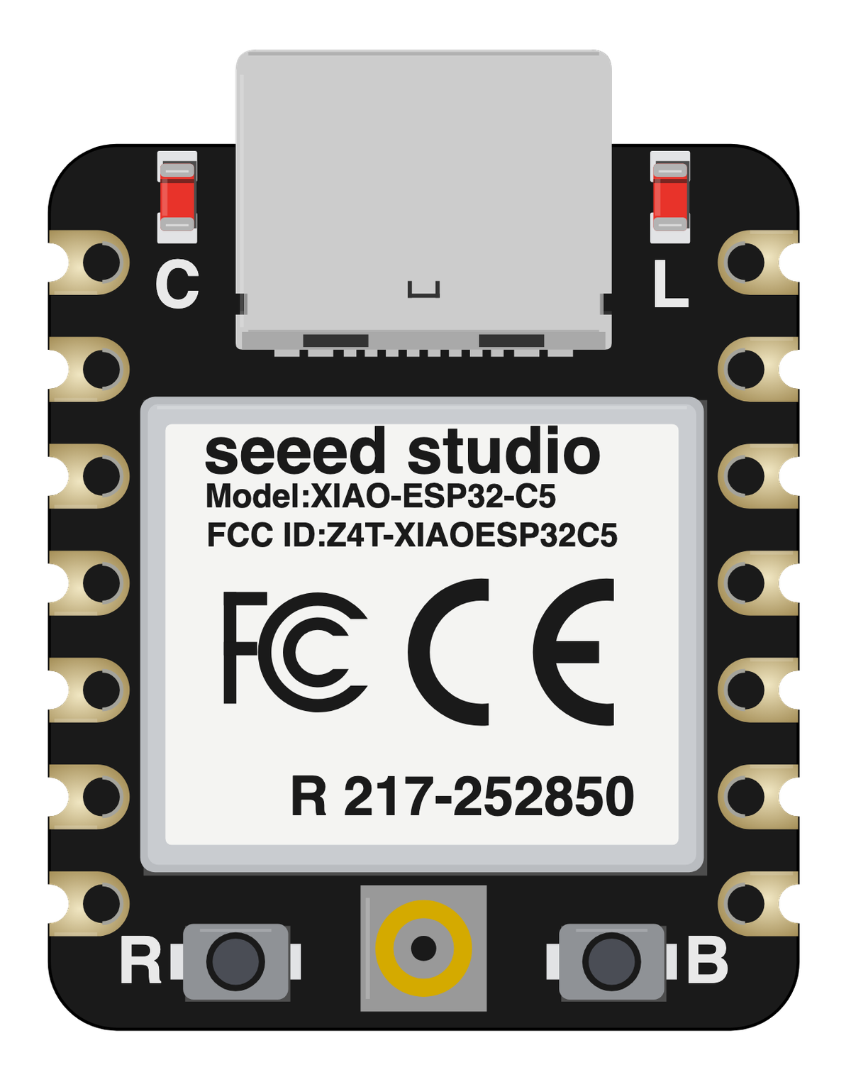
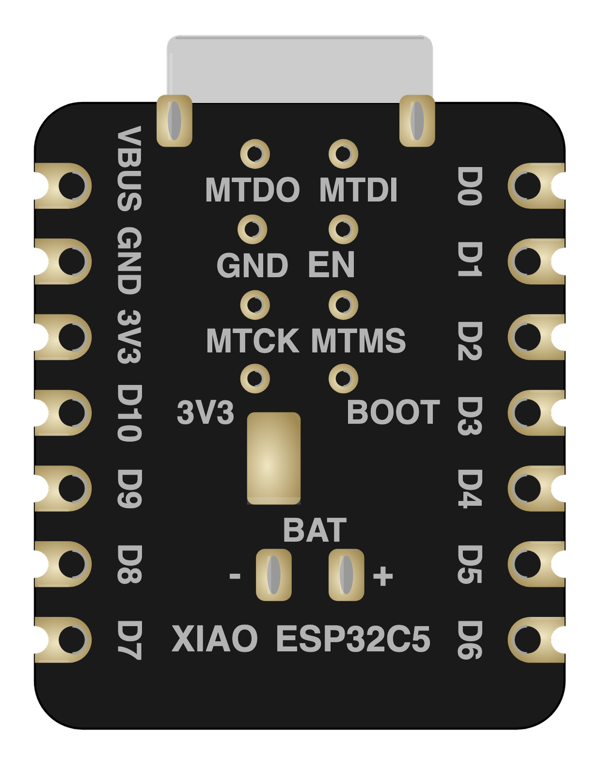
Board illustration
The bare XIAO ESP32C5 board drawn to scale at 21 × 17.8 mm, with no pin labels on it. Made for slide decks, wiring diagrams and project write-ups where a photo is too busy. Take the scalable SVG for print or editing, the high-resolution PNG to drop straight in, or the transparent PNG when you need it with no background behind it.
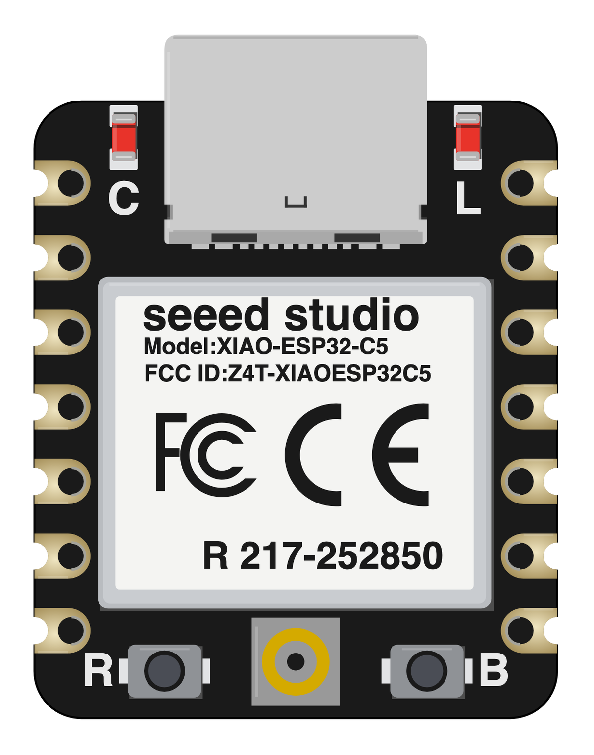
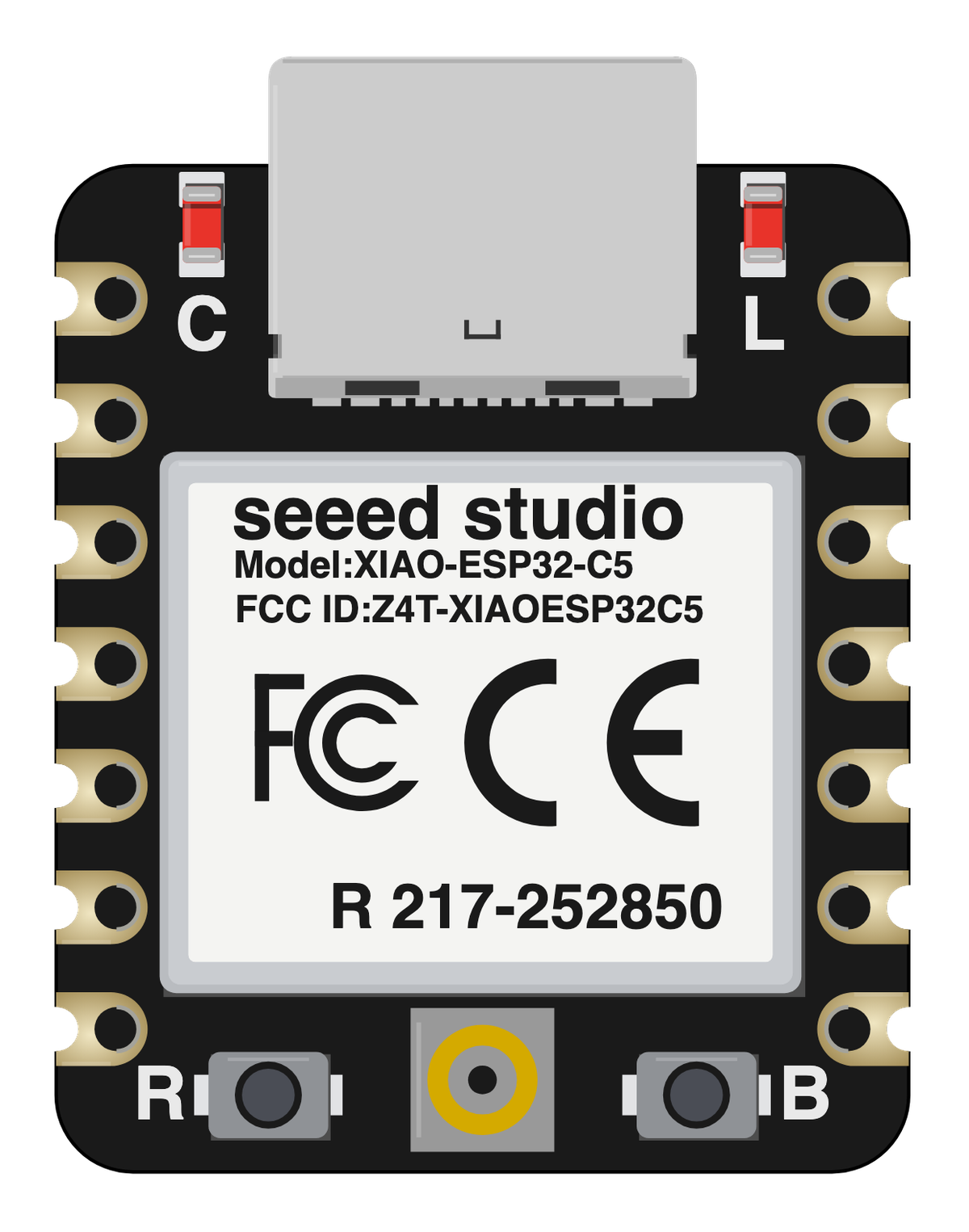
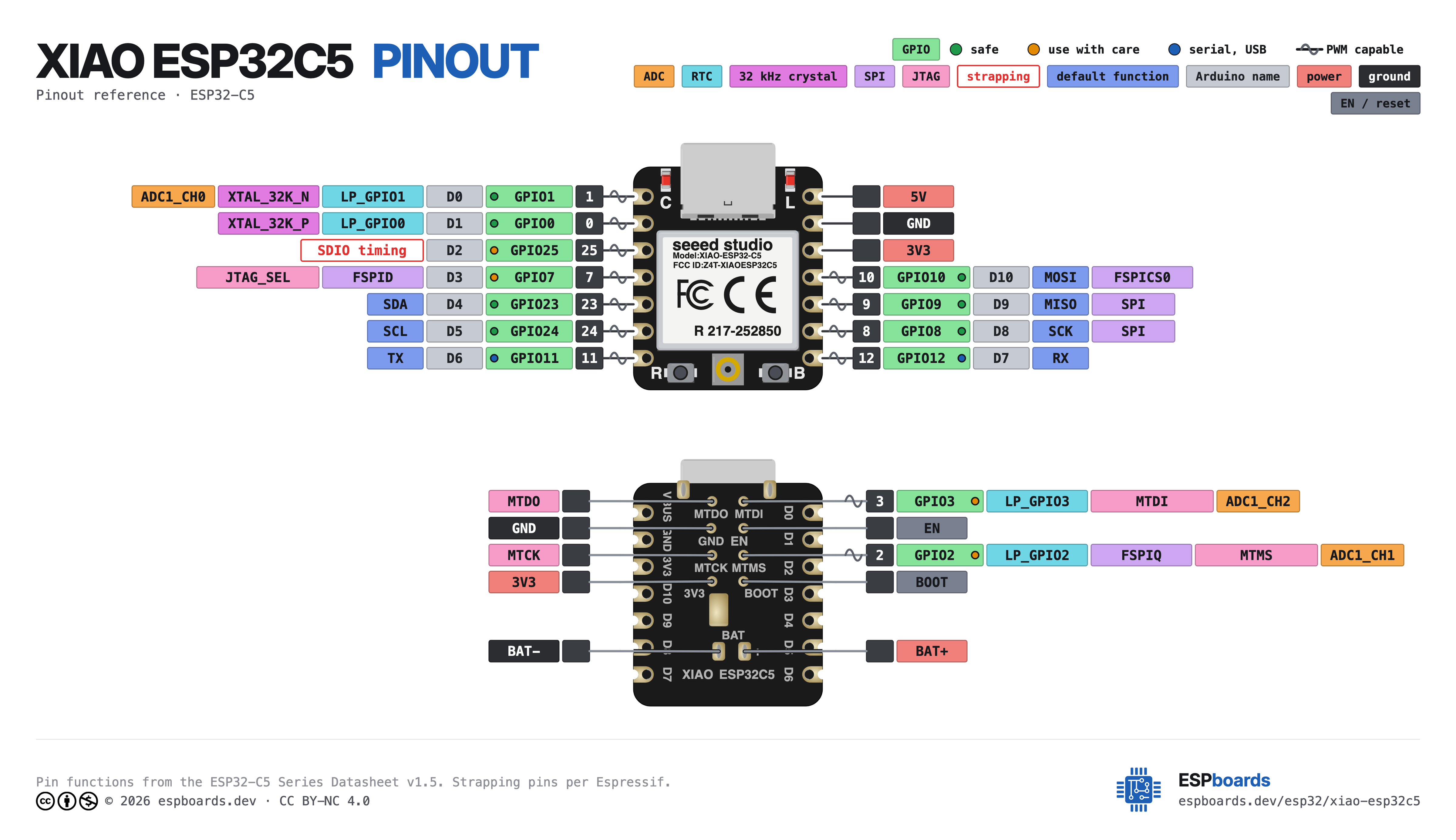
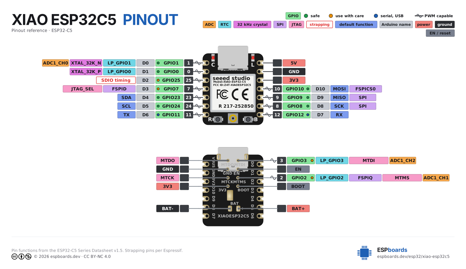
Pinout diagram
Every pin on both sides of the board with its functions, drawn by ESPboards from the ESP32-C5 Series Datasheet v1.5 - the same sheet shown at the top of this page. The PNG is a high-resolution image for screens, the SVG is vector so it stays sharp at any size, and the PDF is laid out to print on A4 or Letter.
Yours to use, share and adapt for non-commercial work, as long as you credit espboards.dev - the full terms and ready-made credit lines are here.
Specifications
ESP32-C5 · 21 × 17.8 mm · vs other ESP32 chips →Dimensions

About this board
At 21 × 17.8 mm it's among the smallest boards in the whole ESP32 family.
Inside sits the ESP32-C5 - a RISC-V part with dual-band 2.4/5 GHz Wi-Fi 6 plus Thread/Zigbee radios.
Around the module: 8MB PSRAM, Zigbee, battery charging (SGM40567) via Solder pads, status LEDs (User, Charge) and Reset/Boot buttons.
It flashes over native USB - no serial-converter driver needed.
The XIAO ESP32C5 is Seeed Studio's thumb-sized (21 x 17.8 mm) board for the ESP32-C5, Espressif's first chip with dual-band Wi-Fi 6. It joins 5 GHz networks as well as 2.4 GHz, which matters in flats and offices where the 2.4 GHz band is saturated, and it keeps Bluetooth 5 LE alongside. The C5 also carries an 802.15.4 radio for Zigbee and Thread.
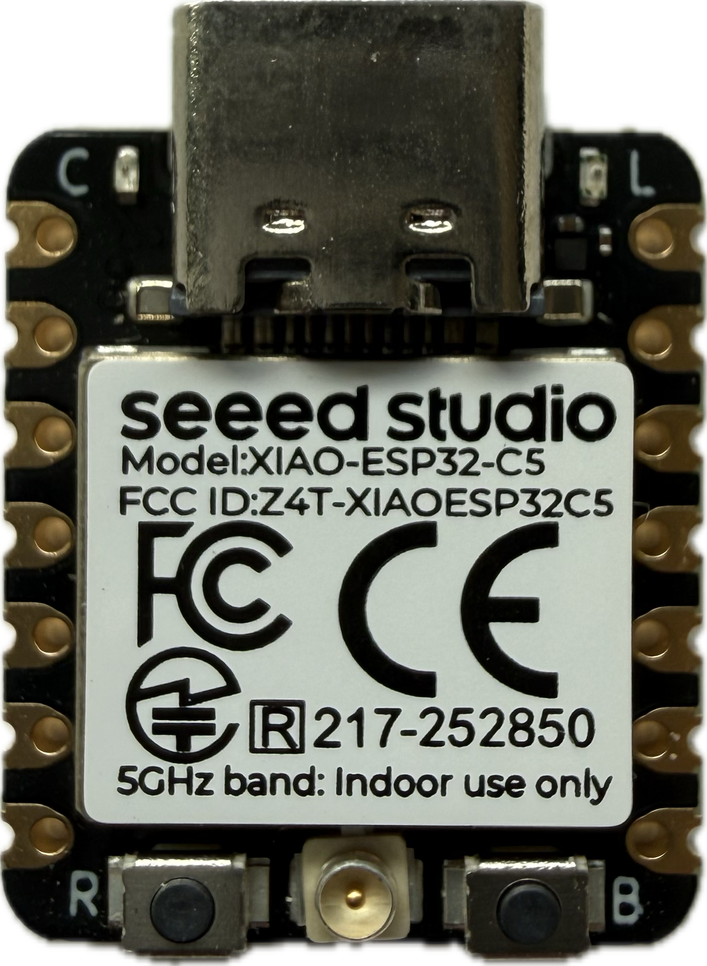
Inside is a 240 MHz RISC-V core with 8 MB of flash and 8 MB of PSRAM. There is no antenna on the board: a u.FL connector takes an external one. Power comes over USB-C or from a 3.7 V lithium cell on the solder pads, with an SGM40567 charger and a charge LED; a user LED sits on GPIO27 and lights when the pin is driven LOW.
Programming runs through the C5's native USB - there is no separate serial chip - and arduino-esp32 3.3 lists the board as XIAO_ESP32C5 with USB CDC On Boot already Enabled, so
Serial.print() reaches the serial monitor out of the box (set it to Disabled and Serial moves to the UART pins D6/D7). A crashed or deep-sleeping sketch takes the USB port down with it; holding BOOT while plugging in always brings it back. Seeed also sells a pre-soldered variant with the headers already fitted.- Dual-band Wi-Fi 6 (2.4 GHz and 5 GHz, 802.11 a/b/g/n/ac/ax) and Bluetooth 5 LE
- 8 MB flash plus 8 MB PSRAM
- Ultra-small XIAO footprint (21 x 17.8 mm), 11 GPIO on the headers
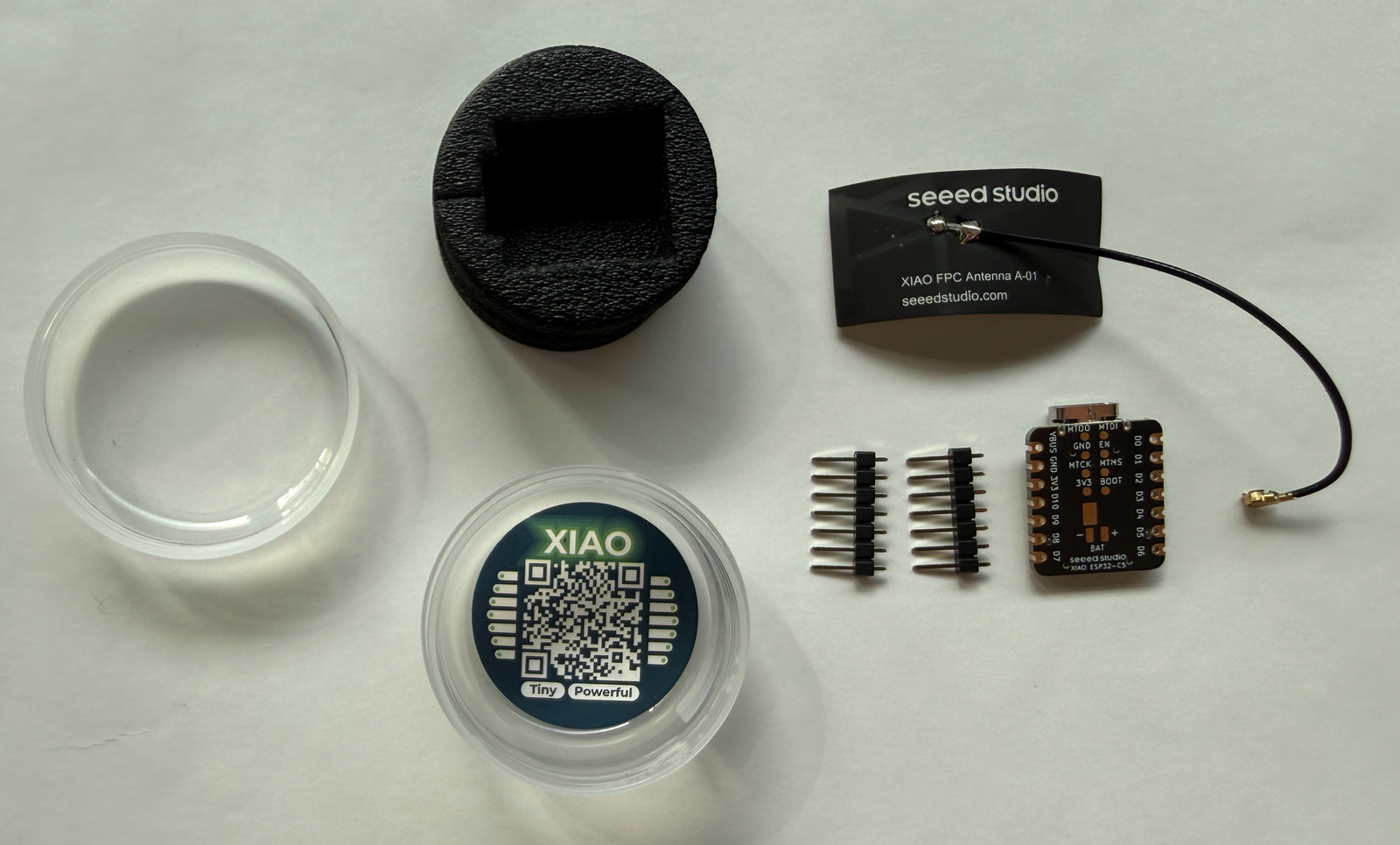
- Ships with an external antenna for the u.FL connector
- LiPo charging via the SGM40567 with a charge LED; battery voltage readable on GPIO6
- [object Object]
Where to buy
prices are typical street prices